
| Tweet |

Custom Search
|
|

|
||
 TM 55-1905-220-14-10
5-20. CYLINDER
BLOCK - MAINTENANCE
INSTRUCTIONS (Continued).
LOCATION
ITEM
ACTION
REMARKS
INSPECT (Cont)
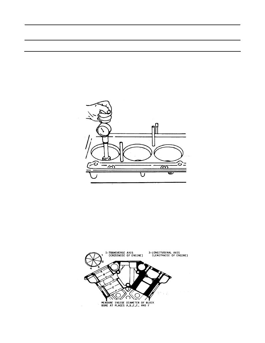
(2) Measure the entire bore of each cylinder with
cylinder bore gage J5347' which has a dial indica-
tor calibrated in .0001 -inch increments. The
standard block bore is 4.6260 inch to 4.6270
inch
(3) First, place the bore gage in the master ring
gage J8386-01 which has an I.D. of 4.6270 inch
and set the dial to zero. Next, rotate the dial
clockwise .0005 inch to give a zero dial indica-
tor setting of 4.6265 inch. Take measurements on
the cleaned-up surface only at positions A, B, C,
D, E and F in the bore on axes 450 apart. Read
the measurements from the zero mark on the gage.
The readings may be recorded on a form similar to
the one illustrated.
5-366
|
||
|
||


