
| Tweet |

Custom Search
|
|

|
||
 TM 55-1905-220-14-10
5-29.1. VOLTAGE REGULATOR-MAINTENANCE INSTRUCTIONS.
a.
General
The voltage regulator is designed for voltage control of AC three-phase generators.
b.
Circuit Description
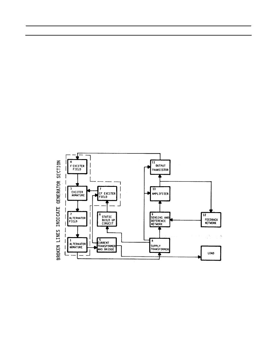
The numbers in parentheses refer to block diagram. The generator voltage output (1) is applied to the
supply transformer (8) which supplies voltage to the static build-up circuit (6). During the build up period, the
static build-up circuit supplies current to the CF exciter field (7). During normal operation, and under short
circuit conditions, the current transformer and bridge (5) also supply current to the CF exciter field. The supply
transformer (8) supplies a sample voltage to the sensing and reference network (9). This network rectifies the
voltage and compares it to a reference. The difference, or error signal, is fed to an amplifier (10) which in turn
controls the output transistor (11). The output transistor acts as a switch and varies the current in the F exciter
field (4) in order to maintain the proper generator output voltage.
The supply transformer (8) also supplies power to the amplifier (10) and output transistor (11). The
feedback network (12) provides for stable operation.
Power flow from the exciter fields (4 and 7) to the exciter armature (3), to the alternator field (2), to the
alternator armature (1) is conventional for ac generators.
5-472
|
||
|
||


