
| Tweet |

Custom Search
|
|

|
||
 TM 55-1905-220-14-11
5-71.
BLOWER - MAINTENANCE INSTRUCTIONS
(Continued).
LOCATION
ITEM
ACTION
REMARKS
OVERHAUL - DISASSEMBLY (Cont)
2. Back out the center
screws of both
pullers and place
the flanges against
the gear faces,
aligning the flange
holes with the
tapped holes in the
gears. Secure the
pullers to the gears
with 5/16"-24xl-1/2"
bolts (two bolts on
the L.H. helix gear,
and three bolts on
the R.H. helix gear).
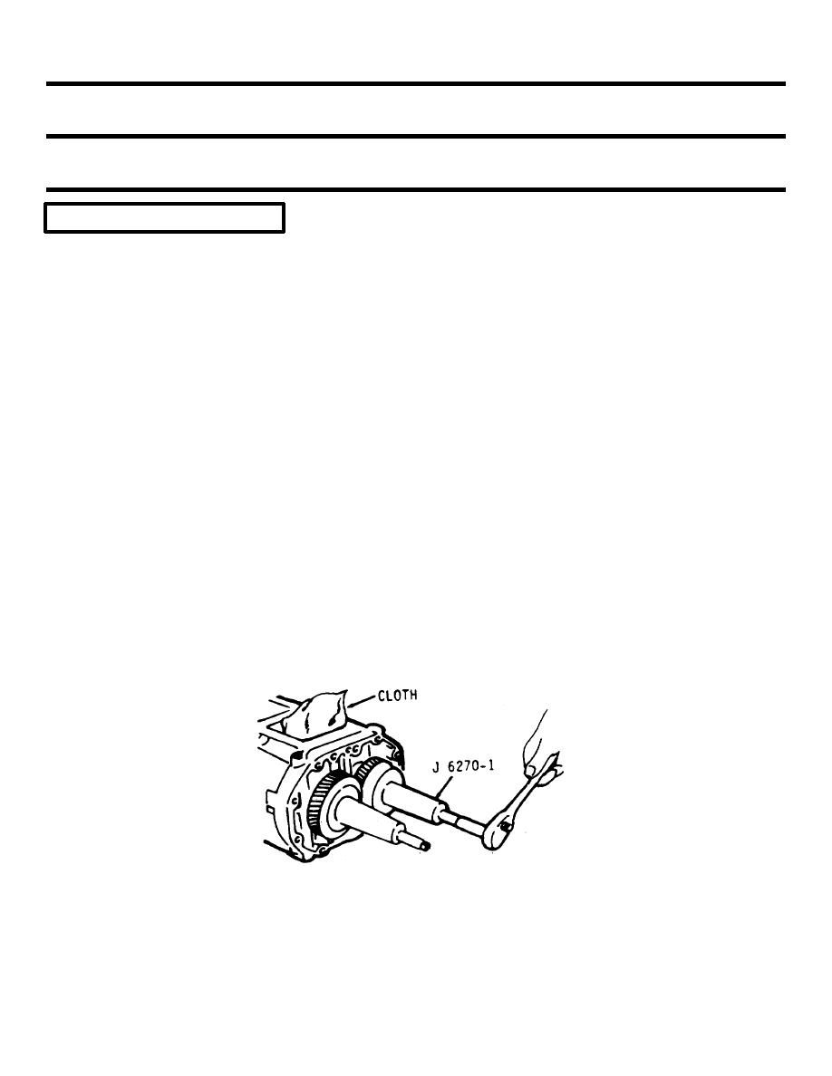
3. With a clean cloth
Use puller
placed between the
J6270-1
rotors to prevent
their turning, turn
the two puller
screws uniformly
clockwise, and with-
draw the gears from
the rotor shafts as
shown below.
5-984
|
||
|
||


