
| Tweet |

Custom Search
|
|

|
||
 TM 55-1905-220-14-11
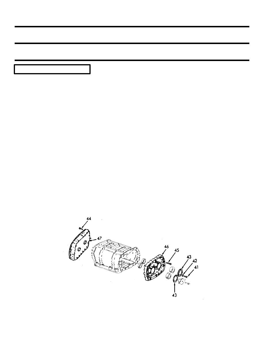
5-71.
BLOWER - MAINTENANCE INSTRUCTIONS
(Continued).
LOCATION
ITEM
ACTION
REMARKS
OVERHAUL - DISASSEMBLY (Cont)
2. Align holes in each
puller flange with
the tapped holes in
the end plate and
secure pullers to
the end plate with
six 1/4"-20x1-1/4"
or longer screws.
NOTE
Be sure that the 1/4"-20 screws are threaded all the way into the tapped holes in the end
plate to provide maximum anchorage for the pullers and to eliminate possible damage to
the end plate.
3. Turn the two puller
screws uniformly
clockwise and with-
draw end plate and
bearings from blower
housing and rotors
as shown.
l.
Front
Remove.
Refer to step k
end plate
above.
(47)
5-987
|
||
|
||


