
| Tweet |

Custom Search
|
|

|
||
 TM 55-1905-220-14-11
5-117. SHIP'S COURSE INDICATOR-MAINTENANCE INSTRUCTIONS (Continued).
6
As the 2.5 degree point is reached, the mixing circuit automatically shifts the amplifier input signal from
1X synchro to 36X synchro. This signal, with amplifier out- put and motor torque reacting accordingly, is
reduced as the servo approaches null. The final null position is reached at the point of minimum 36X synchro
rotor voltage. Because the synchro voltage is very low, the amplifier output and motor torque are reduced
substantially to zero.
7
Mixing networks and anti-stickoff voltages are unnecessary in one-speed systems. Although synchro voltage
(and thus motor torque) go to zero at the 180-degree point, this point is an unstable (decentering) null. If the
servo approaches this false null with slight overshoot, the servo will not come to rest at the null, instead the
servo will continue to rotate toward the true null where it will come to final rest.
(d) 400-CPS servo amplifier.
1
The 400-cps servo amplifier receives electrical position data from one or two synchro control transformers
and delivers electrical power to the servomotor.
2
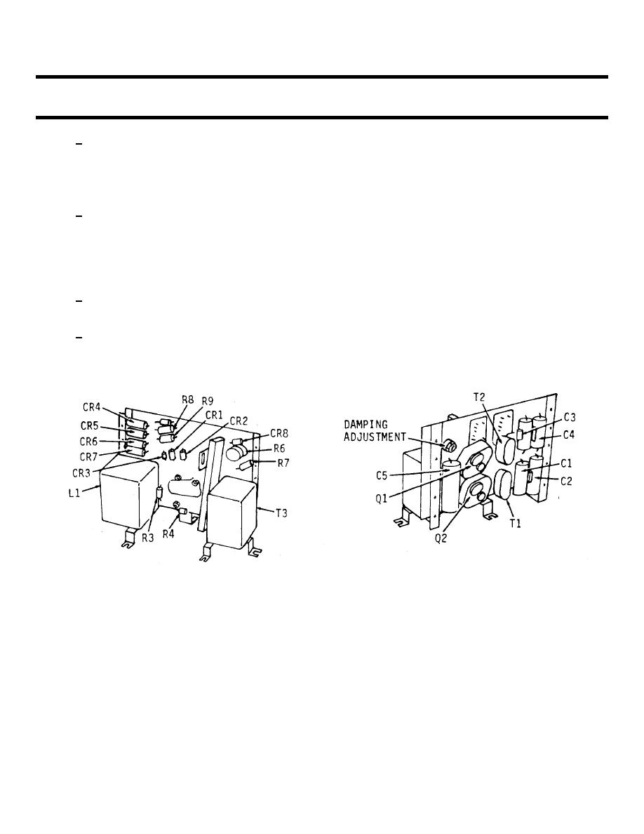
A subchassis within the indicator housing carries the amplifier chassis. All components of the amplifier are
mounted on this chassis including adjustable rheostat R6, which is part of the damping network. The
amplifier contains its own power supply; a separate step-down transformer furnishes power to the dial lamps.
5-1311
|
||
|
||


