
| Tweet |

Custom Search
|
|

|
||
 TM 55-1905-220-14-4
3-10. VARIABLE SPEED MECHANICAL GOVERNOR - MAINTENANCE INSTRUCTIONS - (Cont).
LOCATION
ITEM
ACTION
REMARKS
ADJUSTMENTS (Cont)
b. Remove the bolt connecting the rod and
eye to the stop lever. Align and clamp
the lever to the shutdown shaft in such
a way that, at its mid-travel position,
it is perpendicular to the solenoid
plunger. This assures that the linkage
will travel as straight as possible.
The solenoid plunger has available 1/2"
(1.27 cm) travel which is more than
adequate to move the injector control
racks from the full-fuel to the complete
no-fuel position and shutdown will occur
prior to attaining complete travel.
c. With the stop lever in the run position,
adjust the rod end eye for minimum en-
gagement on the solenoid plunger when
the connecting bolt is installed. The
oversize hole in the eye or clip will
thereby permit the solenoid to start
closing the air gap, with a resultant
build-up of pull-in force prior to
initiating stop lever movement.
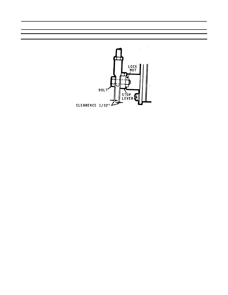
NOTE
The lock nut can be either on top of or below the stop lever.
d. Move the lever to the stop position and
observe the plunger for any possible
bind. If necessary, loosen the mounting
bolts and realign the solenoid to provide
free plunger motion.
3-436
|
||
|
||


