
| Tweet |

Custom Search
|
|

|
||
 TM 55-1905-220-14-4
3-33.1. VALVE AND INJECTOR OPERATING MECHANISM - MAINTENANCE INSTRUCTIONS (Cont).
LOCATION
ITEM
ACTION
REMARKS
REPAIR (Cont)
4. Position the cam follower
body in the groove of the
fixture with a small plunger
extending through the roller
pin hole in the lower leg
of the follower body.
5. Position new cam roller
in the cam follower body.
When released, the plunger
will extend into the roller
bushing and align the rol-
ler with the cam follower
body.
6. Start the new pin in the
cam follower body. Then
carefully tap it in until
it is centered in the cam
follower body.
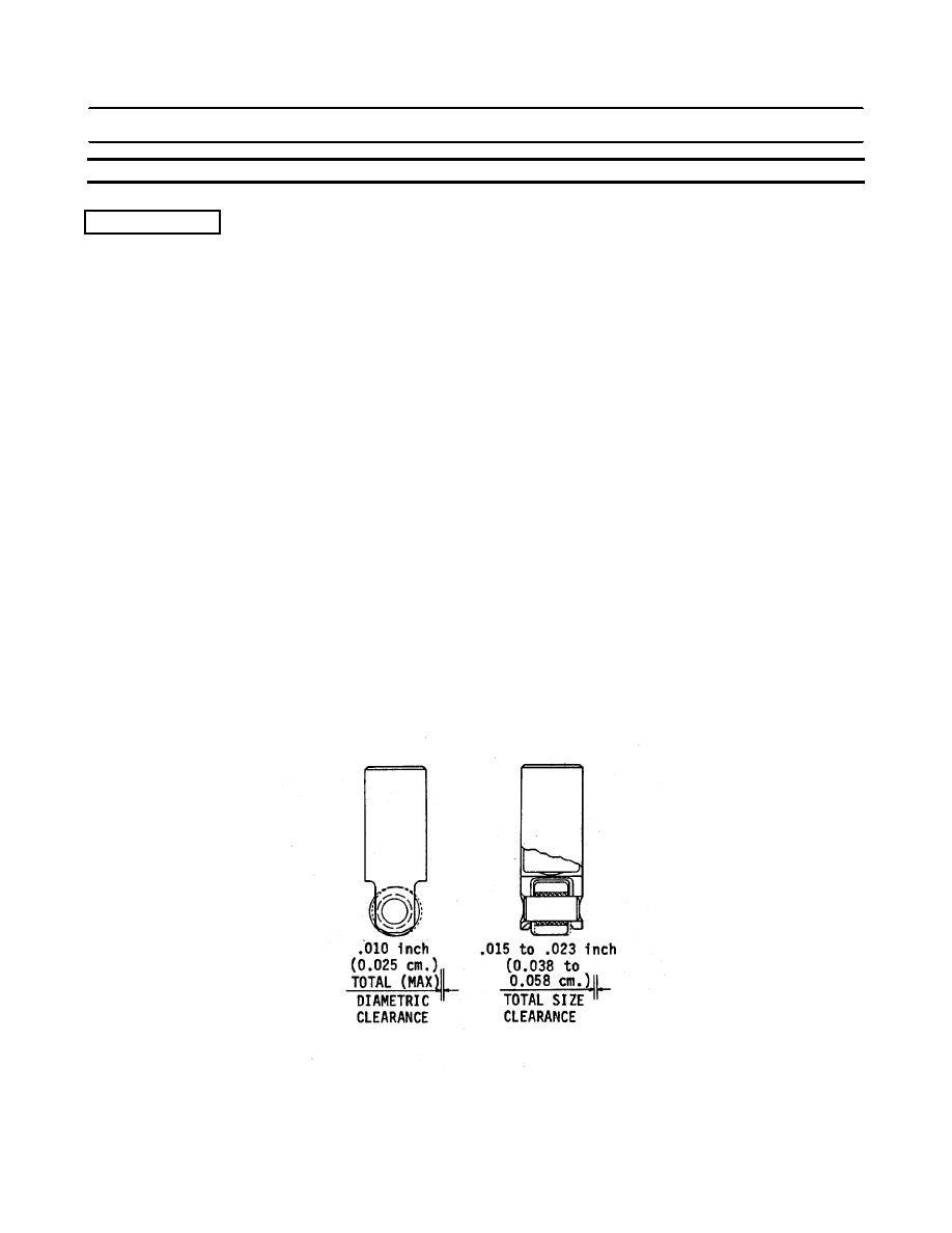
7. Remove the cam follower
from the fixture and
check the side clearance.
The clearance must be
.015 to .023 inch
(0.038 to 0.058 cm).
3-695
|
||
|
||


