
| Tweet |

Custom Search
|
|

|
||
 TM 55-1905-220-14-9
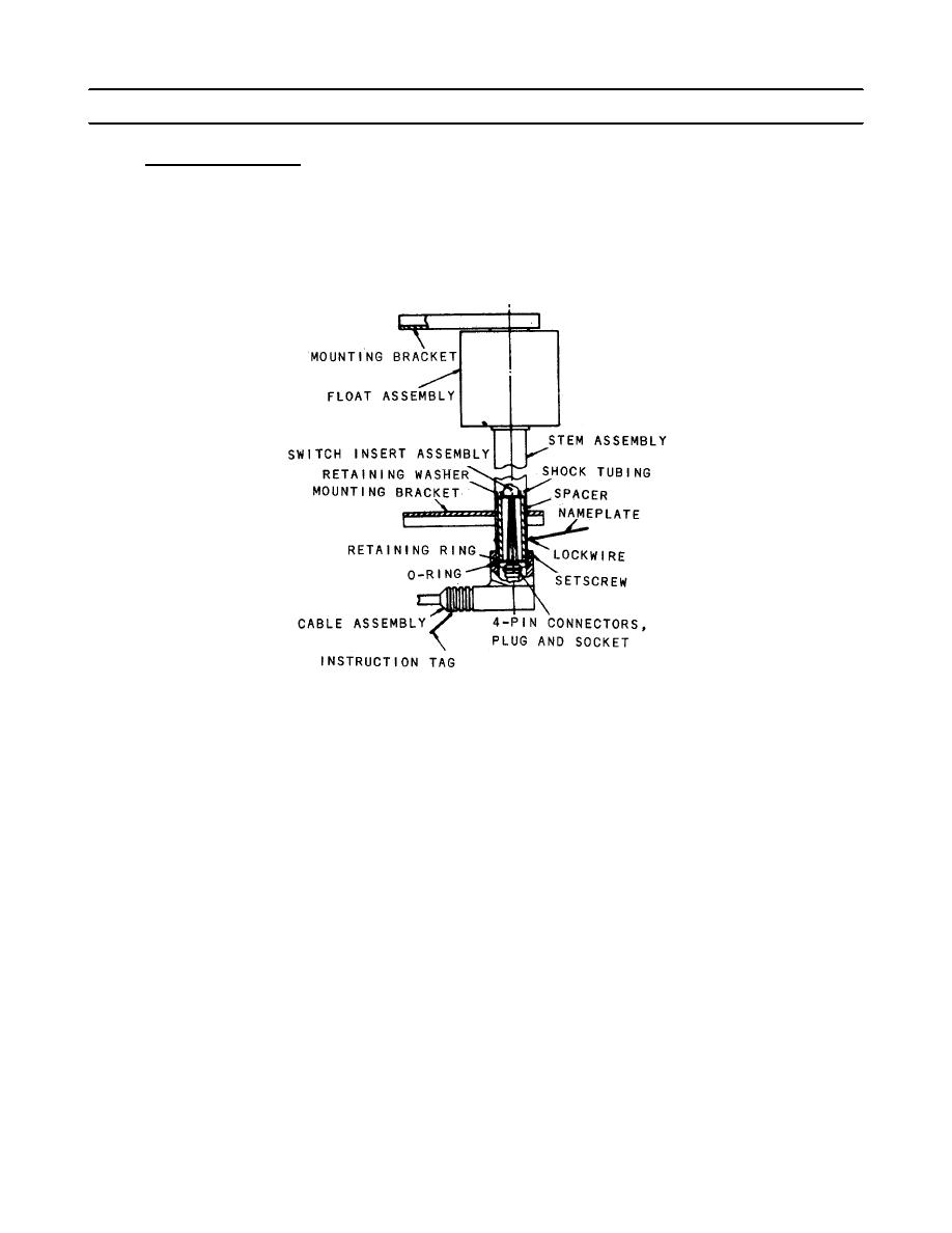
4-66.2. TANK LEVEL INDICATION - TRANSMITTER - MAINTENANCE INSTRUCTIONS (Continued).
b.
Functional Description.
(1) As shown in the cross section view below a typical transmitter contains a voltage divider resistor
network that extends the full length of a transmitter subassembly. Magnetic reed switches are tapped at one-
inch intervals along the height of the resistor network.
(2) As shown in the schematic diagram below, which illustrates two interconnected transmitters the tap
switches are sequentially connected through series resistance to a common conductor. This conductor
connects through the jumper cable to a receiver module or receiver panel via ship's wiring. The top and bottom
of the voltage divider resistor network are connected across the calibration voltage from the calibration network
in the receiver panel or receiver module.
4-1424
|
||
|
||


