
| Tweet |

Custom Search
|
|

|
||
 TM 55-1905-221-14-1
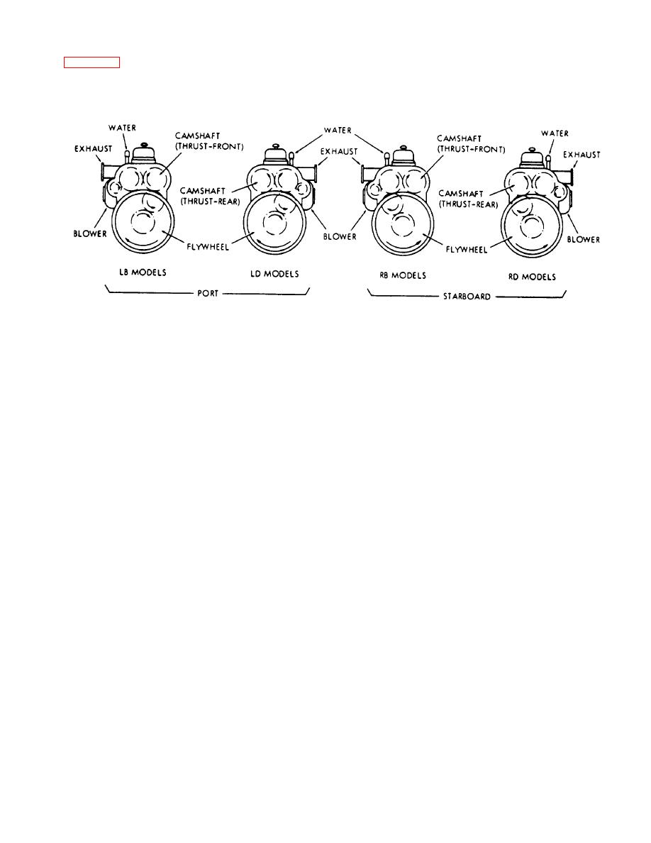
Figure 1-3 illustrates the crankshaft rotation and accessory arrangement of the engines used in each unit. These
views also show the direction of rotation of all gears in the train as well as location of water and exhaust manifolds.
Figure 1-3. Crankshaft Rotation.
1-13.
ENGINE LUBRICATING SYSTEM.
a. Engine lubricating oil is circulated by a gear-type pump gear driven from the crankshaft. All the oil leaving the
pump is forced through the full-flow oil filter to the cooler and then into the oil gallery in the cylinder block where it
is distributed to the various engine bearings. The drain from the cylinder head and other engine parts leads back
to the oil pan.
b. If the oil cooler should become clogged, the oil will flow from the pump through a spring loaded bypass valve
directly into the oil gallery.
c. Stabilized lubricating oil pressure is maintained within the engine at all speeds, regardless of the oil temperature,
by means of a regulator valve located between the pump outlet and the inlet to the cylinder block. When the oil
pressure at the valve exceeds 50 pounds per square inch, the regulator valve opens and remains open until the
pressure is less than the opening pressure.
1-40
|
||
|
||


