
| Tweet |

Custom Search
|
|

|
||
 TM 55-1905-221-14-1
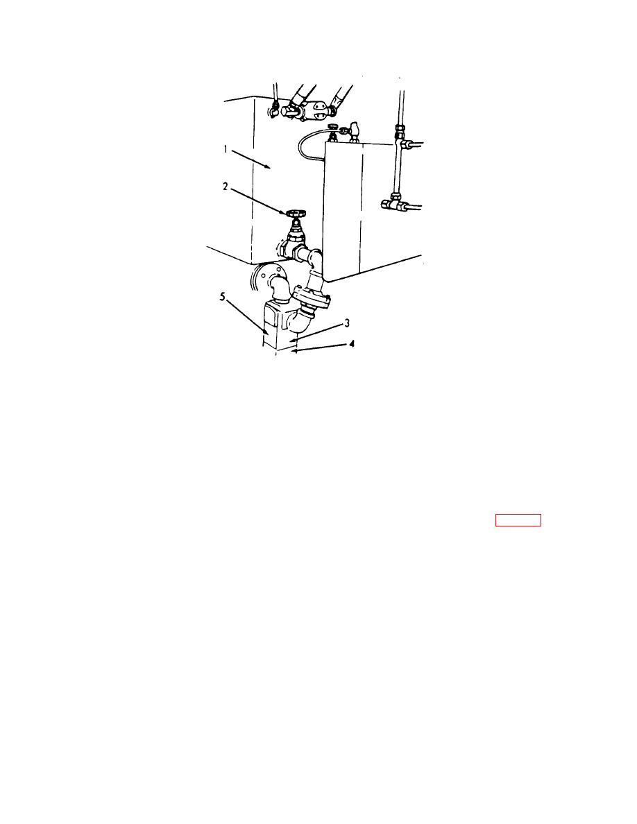
1.
Hydraulic tank
3.
Suction strainer
2.
Gate valve
4.
Strainer cover
5.
Condition indicator
Figure 2-23. Ramp Hoist Hydraulic System Suction Strainer.
(3) Operate only one ramp hoist pump at a time.
b. Normal Operation to Lower Ramp.
(1) Be sure the supply valve, located at the bottom of the ramp hoist system tank, is open.
(2) With engine running, start hydraulic ramp hoist pump (one only) by engaging clutch (fig. 2-16).
2-53
|
||
|
||


