
| Tweet |

Custom Search
|
|

|
||
 TM 55-1905-221-14-3
6-26.1.
LUBE OIL PUMP ASSEMBLY - MAINTENANCE INSTRUCTIONS
(CONTINUED).
LOCATION/ITEM
ACTION
REMARKS
INSTALLATION
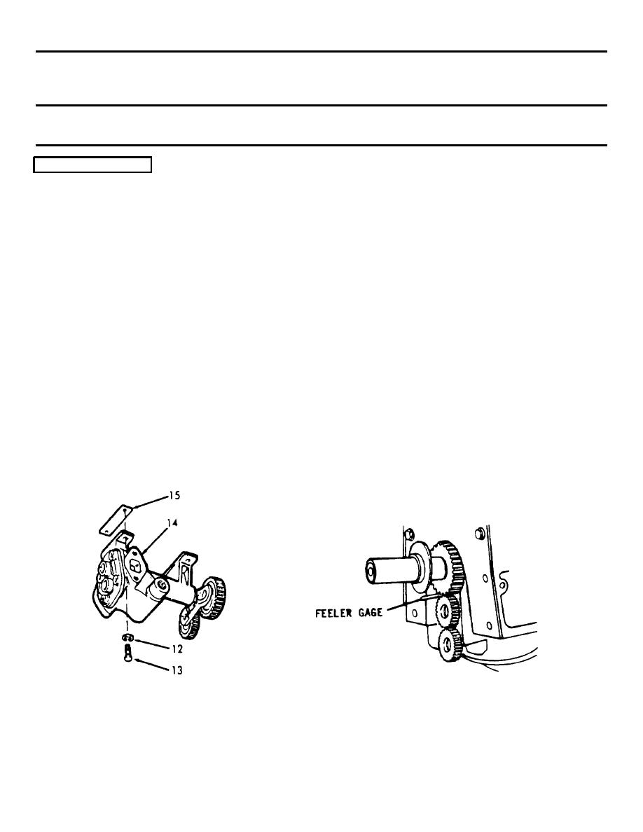
5.
a. Hold the oil pump (14) and
shim (15) against the main
bearing caps so the idler
gear meshes with the driving
gear on the crankshaft.
b. Insert the four screws (12),
and lockwashers (13) through
the mounting feet of the
pump and into the bearing
caps. Align the pump so that
the teeth of the crankshaft
gear and the idler gear are
parallel; then tighten the
bolts to 35-39 ft-lb (47.8-
53.2 Nm) and check clearance
between the gear teeth with
a feeler gage. Proper clear-
ance between the crankshaft
gear and the idler gear is
.005 inch (0.013 cm) mini-
mum - .012 inch (0.030 cm)
maximum.
6-406
|
||
|
||


