
| Tweet |

Custom Search
|
|

|
||
 TM 55-1905-221-14-4
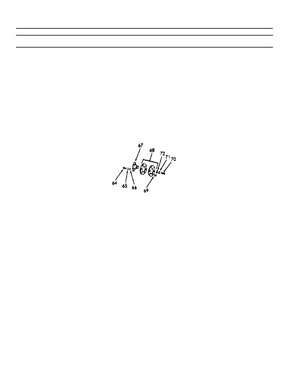
6-35. BLOWER ASSEMBLY (Continued).
LOCATION/ITEM
ACTION
REMARKS
DISASSEMBLY (Cont)
17. Blower Rotor
a. Remove bolts (64), lockwashers
Drive Hub,
(65), and flatwashers (66),
Plates and
securing drive hub (67) and
Spacers.
plates (68) to timing gear.
b. Remove drive hub (67), plates
Plates will be
(68), and spacers (69), from
attached to hub.
timing gear.
c. Remove bolts (70), lock-
If plates are
washers (71), and flatwashers
damaged.
(72) securing drive plates
(68) together.
18. Blower Rotor
a. Remove capscrew (73), key
Timing Gear
washer (74), and hex washer
(75) from right-hand helix
rotor shaft.
b. Remove capscrew (73), key
washer (74), and fuel pump
rotor disc (76) from left
hand rotor shaft.
c. Back out center screw on gear
Use pullers
pullers and secure to gears
J6270-1.
with 5/16"x24x1-1/2" bolts.
NOTE
Both gears must be pulled from the rotor shafts at the same time.
6-650
|
||
|
||


