
| Tweet |

Custom Search
|
|

|
||
 TM 55-1905-221-14-4
6-35. BLOWER ASSEMBLY (Continued).
LOCATION/ITEM
ACTION
REMARKS
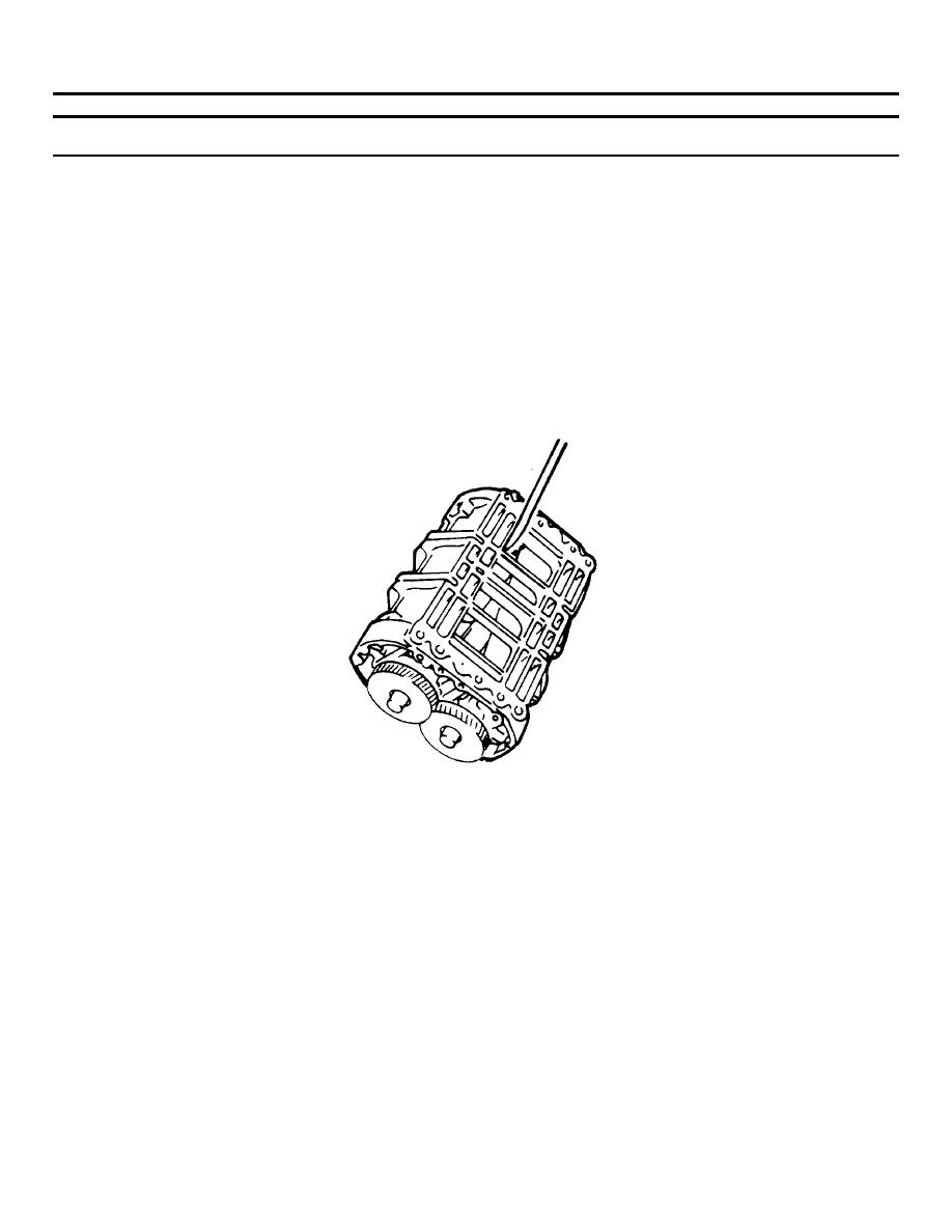
REASSEMBLY (Cont)
(4)
Determine the minimum
clearances at points
"A" and "B" as shown.
Insert the feeler gages
between the end plates
and the ends of the
rotors. This operation
must be performed at
the ends of each lobe,
making twelve measure-
ments in all.
(5)
Check the clearance
between each rotor lobe
and the blower housing
at both the inlet and
outlet side - twelve
measurements in all.
See figure below for
minimum clearances.
6-690
|
||
|
||


