
| Tweet |

Custom Search
|
|

|
||
 TM 55-1905-221-14-4
6-37. POWER TAKE-OFF ASSEMBLY (Continued).
LOCATION/ITEM
ACTION
REMARKS
DISASSEMBLY
4. Power
a. Remove screws (30), inspection
Expose the
Take-Off
hole cover (31), and gasket
adjusting ring
(32).
(20), and
linkage (26).
b. Hold the outer end of the
flexible grease tube (33) from
turning (inside of clutch
housing) and remove the flexible
tube retaining nut.
c. Pull the outer end of flexible
grease tube (33) inside of the
clutch housing and remove the
opposite end from the release
sleeve collar.
d. Support the power take-off
assembly on wood blocks with
the clutch drive shaft in a
horizontal position. Then,
bend the edge of the lockwasher
(34) up off the flat side of the
clutch drive shaft nut (17).
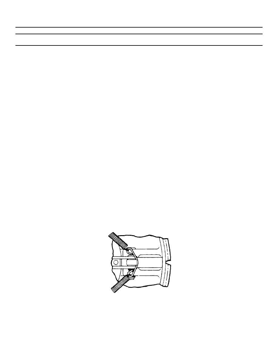
e. Disengage the clutch with the
hand lever.
f. Slide the "garter" type clutch
release lever spring (25) off
the clutch release levers (27)
and on the release sleeve (21).
6-745
|
||
|
||


