
| Tweet |

Custom Search
|
|

|
||
 TM 55-1905-221-14-4
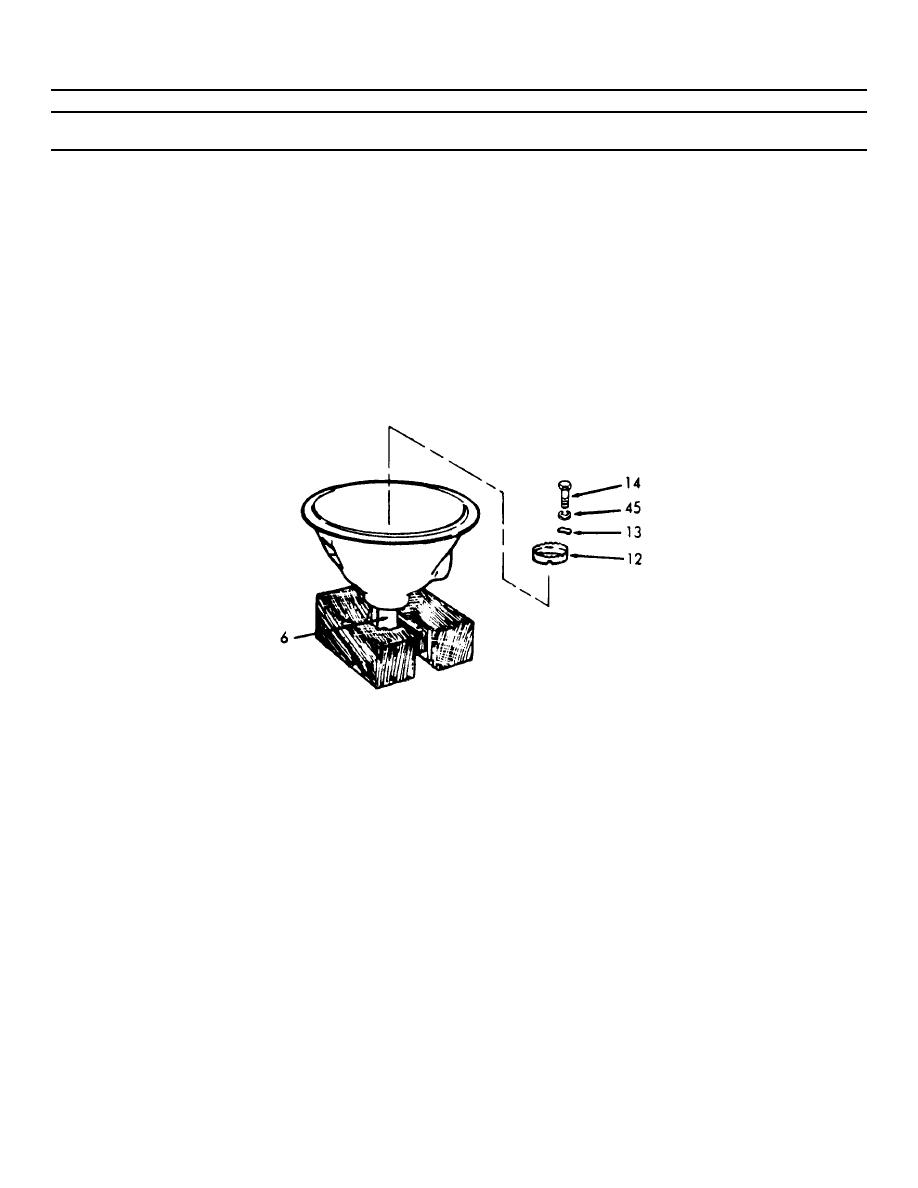
6-37. POWER TAKE-OFF ASSEMBLY (Continued).
LOCATION/ITEM
ACTION
REMARKS
REASSEMBLY (Cont)
i. Thread the bearing retainer (12)
into the bearing bore until it
is against the bearing cup.
Tighten the bearing retainer
while rotating the drive shaft
(6) until the bearing retainer
is tight and the bearing cups
are seated. When the bearing
cups are seated it will be noted
by the increase effort required
to rotate the drive shaft.
j. Back the bearing retainer (12)
out 2 or 3 notches.
k. Install retainer lock plates
(13), lockwashers (45) and bolts
(14).
l. Support the clutch housing and
shaft assembly on wood blocks
with the outer end of the clutch
drive shaft up. Then, tap on
the outer end of the drive shaft
with a plastic hammer to force
the roller bearing cup down
until the bearing cup seats
on the bearing retainer.
6-771
|
||
|
||


