
| Tweet |

Custom Search
|
|

|
||
 TM 55-1905-221-14-4
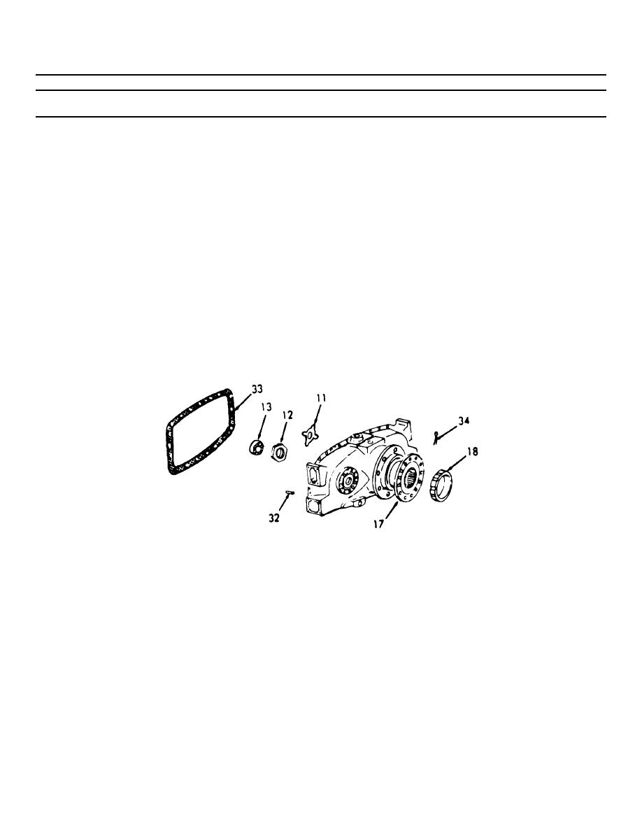
6-38. TRANSFER GEAR ASSEMBLY (Continued).
LOCATION/ITEM
ACTION
REMARKS
DISASSEMBLY (Cont)
8.
Insert a 1/2 inch
Through the one
square drive short
inch hole in
extension. Then
the supporting
attach a flex handle.
member.
9.
While holding the
Turn the next
transfer gear housing
counterclock-
in a fixed position
wise.
loosen the driven gear
locknut (12).
e. Loosen the drive flange
1. Use the same
locknut (18).
procedure as
in step d.
above.
2. Use wrench
J4384-01.
6-799
|
||
|
||


