
| Tweet |

Custom Search
|
|

|
||
 TM 55-1905-221-14-4
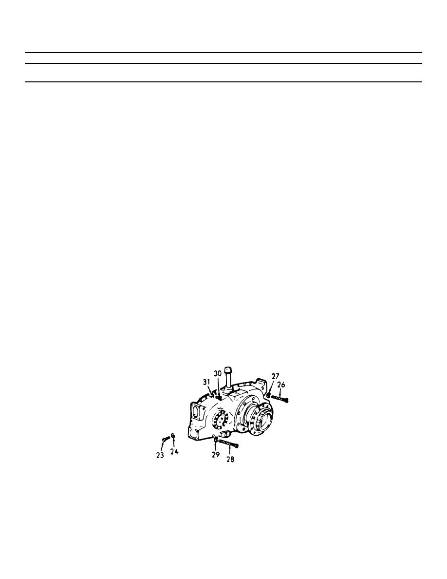
6-38. TRANSFER GEAR ASSEMBLY (Continued).
LOCATION/ITEM
ACTION
REMARKS
INSTALLATION (Cont)
j. Lower the unit so it rests on
the side rails. Align the bolt
holes in the side rail with the
bolt holes in the flywheel and
transfer gear housings. Then,
install the two side rails to
the flywheel housing bolts (26)
with lockwashers on each engine,
and the four side rails to gear
housing bolts (23) with lock-
washers (24) at each side of the
gear housing.
k. Tighten the side rail to the
flywheel housing and gear
housing bolts (23) to 71-75
ft-lb (96.2-101.7 Nm) torque.
l. Tighten the front support
bracket to side rail bolt nuts
(25) to 83-93 ft-lb (112.5-126.1
Nm) torque.
m. If not previously tightened, the
drive shaft bearing cover bolts
should be tightened to 40-45
ft-lb (54.2-61.0 Nm) torque.
n. Remove the chain hoist and sling
from the engine lifting brackets.
6-825
|
||
|
||


