
| Tweet |

Custom Search
|
|

|
||
 TM 55-1905-221-14-4
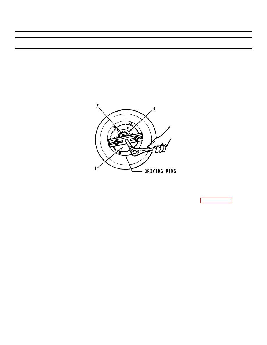
6-41. POWER TAKE OFF COUPLING AND VIBRATION DAMPER (Continued).
LOCATION/ITEM
ACTION
REMARKS
REMOVAL (Cont)
f. Attach a bar type puller
J4558 to the coupling flange
with two long 3/8"-16 bolts,
with the center screw of the
puller in the center of the
bolt (7) head in the crank-
shaft as shown below.
g. Turn the center screw and
The driving ring
pull the coupling assembly
is part of the
(4), accessory pulley (9),
power take-off
drive adapter (1) and driving
assembly. Refer
ring as an assembly from the
crankshaft as shown above.
h. Remove the remaining bolts
(2) and lockwashers (3)
securing the clutch drive
adapter (1) and the accessory
drive pulley (9) to the
flange of the drive coupling
assembly (4), then remove the
drive adapter and accessory
pulley from the coupling.
i. Remove the Woodruff keys (10)
from the keyways in the
crankshaft.
6-922
|
||
|
||


