
| Tweet |

Custom Search
|
|

|
||
 TM 55-1905-222-14
f.
The navigation lights are controlled by a double pole, double throw switch (DPDT) located in the control and
distribution panel. A stern light, two side lights (port and starboard), four not-under-command lights, an anchor light and
masthead light comprise the navigation lights. These lighting circuits are protected by panel installed 10A fuses. The
masthead, anchor and not-under-command light-; are mounted on a telescoping mast hinge-mounted on deck aft of the
pilothouse. The mast lighting circuits are completed through plugs and receptacles Installed on the aft side of the
pilothouse. An induction compass transmitter for the RMHS is located on top of the mast support (see illustration on
facing page)
g.
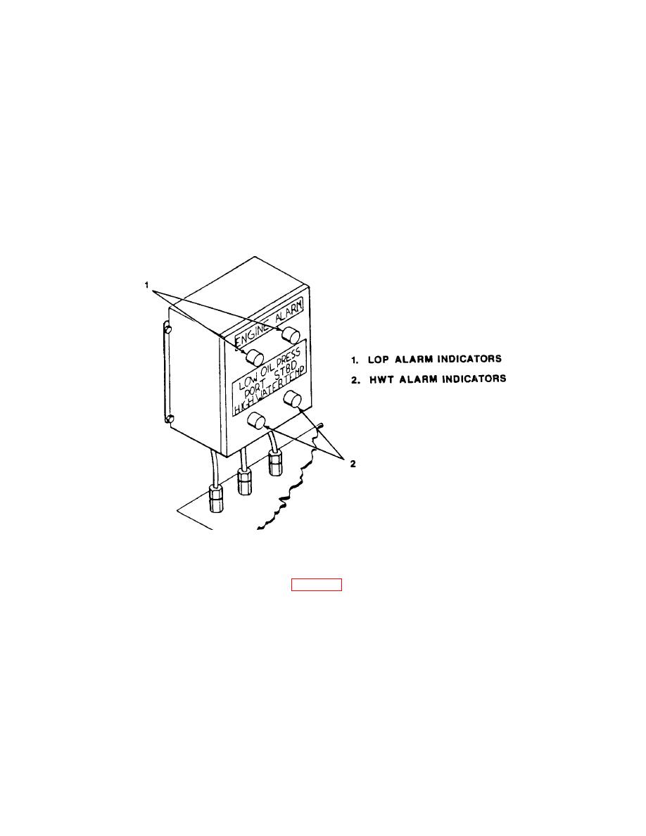
The engine alarm panel provides the helmsman with a visual alarm In the event of an engine malfunction.
The engine alarm circuits are controlled by a DPST switch and protected by two 10A fuses on the control and distribution
panel. The alarm circuits consist of engine warning red indicating lamps (RIL) which indicate low oil pressure (LOP) and
high water temperature (HWT). The LOP alarm circuit contains a fuel pressure switch which prevents the LOP circuit
from activating when the engines are shut down. A ground detector, located in the pilothouse, is used to detect grounds
in the entire electrical system excluding the IC circuits.
NOTE
The location of electrical components inside the pilothouse
are shown and described in para. 2-1.
1-34
|
||
|
||


