
| Tweet |

Custom Search
|
|

|
||
 TM 55-1905-222-14
MAINTENANCE OF CLUTCH LINKAGE
4-24
ADJUST CLUTCH LINKAGE.
The aim of this adjustment is to ensure that the output motion generated by the transmission control unit is compatible
with the required stroke for the clutch control valve lever. It is also important that the clutch control valve lever goes
from neutral to both "gear engage" positions without bottoming. A slight amount of end play is essential.
INITIAL SETUP
Tools:
Equipment Conditions:
Tool Kit, Mechanic's, Rail
Reference
and Marine
ADJUST CLUTCH LINKAGE.
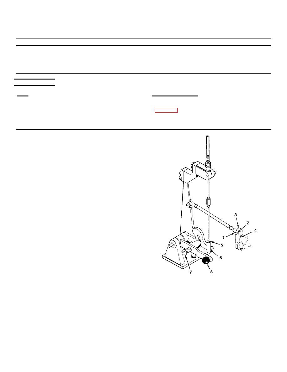
a.
Remove hex nut (1), lockwasher (2), and rod
end (3) from the clutch control valve lever (4).
b.
Move the clutch control valve lever (4) into the
FWD and REVERSE positions. Scribe marks
to denote the gear positions.
c.
Take measurement between the FWD and
REV gear positions. Clutch travel should be
3 inches.
d.
Re-connect rod end (3) to clutch control valve
lever (4) using hex nut (1) and lockwasher (2).
e.
Observe position of clutch control valve lever
(4) as propulsion control lever in pilot house is
cycled into FWD and REV gear positions.
The clutch control valve lever (4) should go
from NEUTRAL to both "gear engage" positions
without bottoming.
4-47
|
||
|
||


