
| Tweet |

Custom Search
|
|

|
||
 TM 55-1905-222-14
5-11 REPLACE HYDRAULIC GAUGES, RUDDER ANGLE INDICATOR AND ANINIETER.
This task covers:
a. Removal
c. Adjustment
b. Installation
INITIAL SETUP
Tools:
Equipment Conditions:
Tool Kit, Mechanic's, Rail
All power off
and Marine
General Safety Instructions:
Materials/Parts:
Hydraulic Steering Gauge
Ensure that hydraulic pressure in the
P/N 5DFMI-4CBM3000
system is relieved before removing gauges.
Hydraulic Ramp Gauge
P/N5DFM1-4CBM5000
Use a tester to ensure that all power
Hydraulic Start Gauge
is off before touching bare wires.
P/N 5DFMI-4CBM5000
Battery Ammeter
P/N 377GH10
Rudder Angle Indicator
P/N MDL150,520-012
Adhesive (RTV)
Item 18, Appendix E
REMOVAL
1.
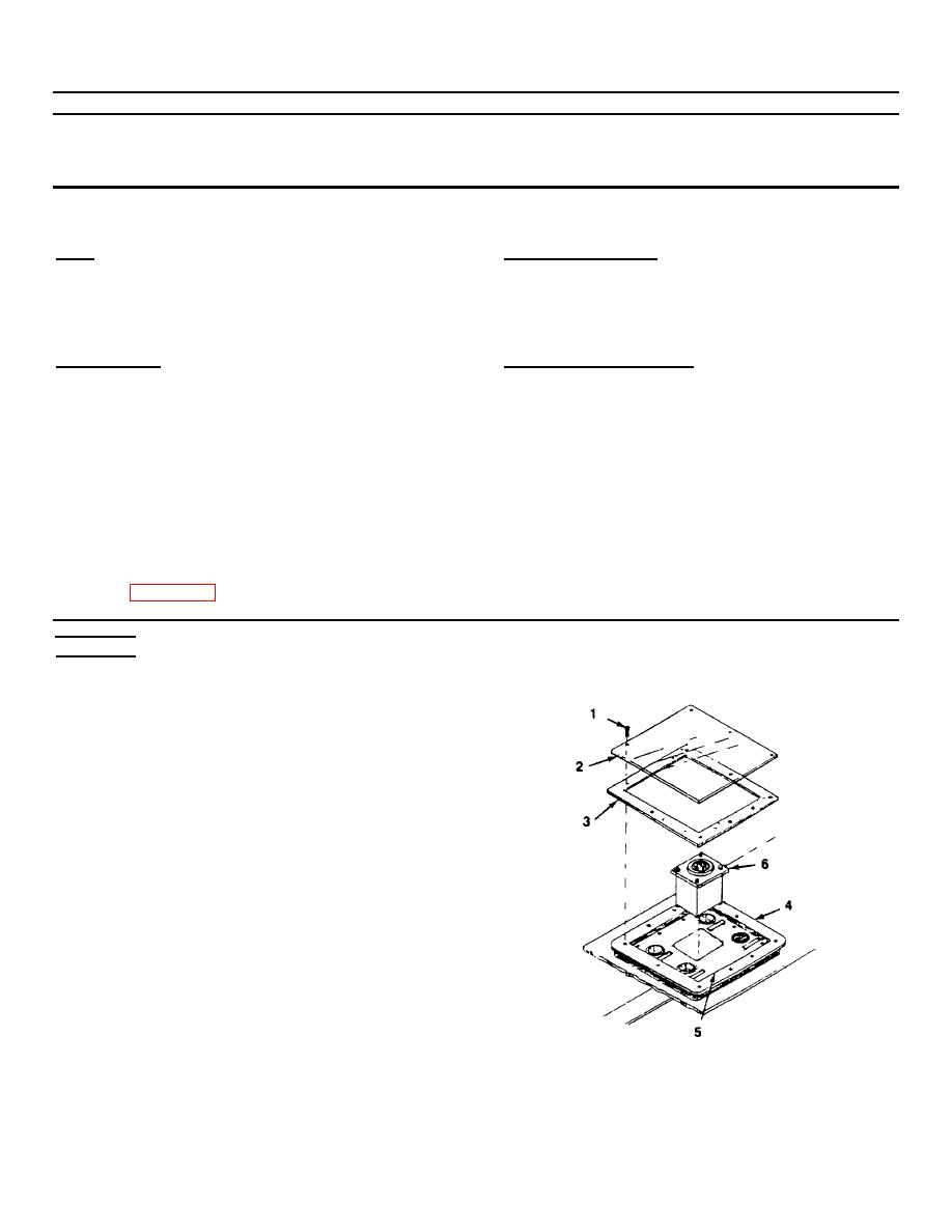
REMOVE COVER GLASS AND GASKET.
Loosen fourteen tapping screws (1) and remove
cover glass (2) and gasket (3) from the angle plate
(4).
2.
REMOVE RUDDER ANGLE INDICATOR.
a.
The rudder angle indicator is attached to the
instrument panel by adhesive.
Use a small
flathead screwdriver to detach rudder angle
indicator from the instrument panel (5).
Lift
indicator only enough to obtain enough clearance
to the rear of indicator (6).
5-28
|
||
|
||


