
| Tweet |

Custom Search
|
|

|
||
 TM 55-1905-222-14
6-14
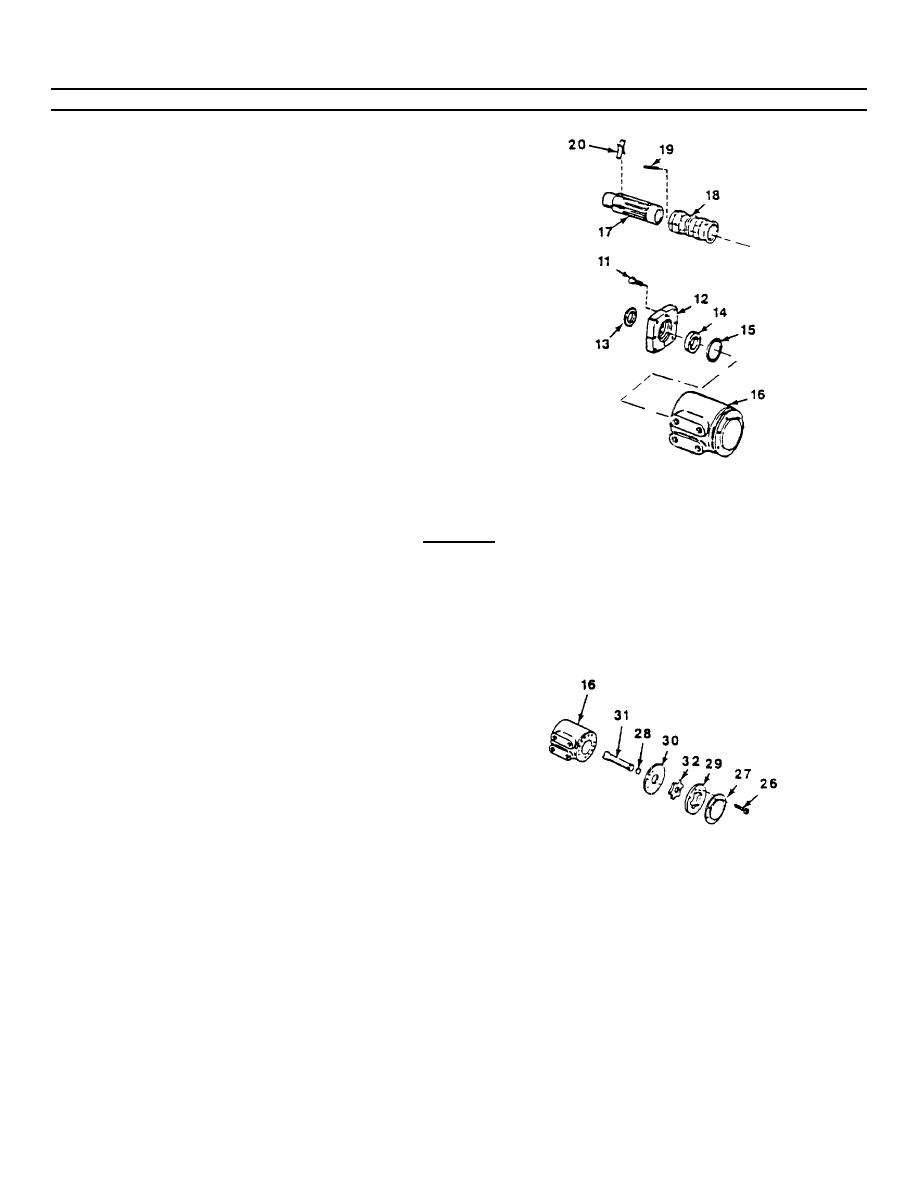
REPAIR HELM UNIT (Continued).
f.
Align spring slots of control spool (17) and
sleeve (18) and install spring set (20) using
spring installation tool J600057.
g.
Install centering pin (19) through control spool
and sleeve assembly
h.
Install control spool and sleeve assembly in
housing (16) so that the splined end of the spool
enters first With the control spool and sleeve
assembly. in this flush position, check for
free rotation within the housing.
i.
Install new preformed packing (15) and bushing
(14) on housing (16).
j.
Install oil seal (13) in counter bore of mounting
plate (12) and install mounting
plate on
housing (16) Secure with four capscrews
(11). Torque evenly to 250 pound-inches.
2.
ASSEMBLE METERING SECTION.
CAUTION
Alignment of the cross slot in the drive with valleys between the teeth of the meter
gear star determines proper valve timing of the unit. There are 12 teeth on the
spline and 6 pump teeth on the star. Alignment is exactly right in 6 positions
and exactly wrong in 6 positions. If the parts slip out of position during this part of
the assembly, repeat until you are certain that correct alignment is obtained.
a.
Place the plate (30) over the housing (16)
so that both holes in the plate align with the
tapped holes in the housing
Place the
meter gear (29) on the assembly as the bolt
holes align
6-78
|
||
|
||


