
| Tweet |

Custom Search
|
|

|
||
 TM 55-1905-222-14
6-24
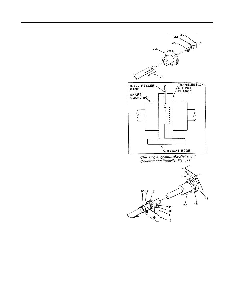
ALIGN PROPELLER AND PROPELLER SHAFT (Continued).
near the suspected area on the shaft.
Feelers are inserted between the coupling
flanges, and if there is a greater distance
between the faces at one part of the
coupling than at another, the shafts are out
of alignment at these places.
e. Place a straight edge across edges of
flanges at top and side to check parallel
alignment of coupling edges.
f.
Place a 0.002-inch feeler gauge between
flanges of coupling and slide feeler gauge
completely around coupling.
g. Rotate transmission flange coupling 90,
180 and 270 degrees while moving feeler
gauge around the flange in each
successive position. If the alignment is
correct, the feeler gauge will fit snugly, with
same tension all around flange coupling.
h. Bolt transmission output flange and shaft
coupling (20) together with eight bolts (18)
and nuts (19).
6-133
|
||
|
||


