
| Tweet |

Custom Search
|
|

|
||
 TM 55-1905-223-24-1
e. Clean parts with solvent. Ensure all oil drillings are open and free from
blockage.
f.
Measure the inside diameter of the sleeve bushings (6). Ensure inside
diameter is between 1.751 inch (44.48 mm) and 1.755 inch (44.58 mm). If the
inside diameter of either bushing is not within specifications, replace both
bushings as follows:
(1) Support the housing (14) with an arbor press.
(2) Use a mandrel to remove the bushings (6).
(3) Measure the inside diameter of the housing bore. Verify inside diameter
is between 1.875 inch (47.63 mm) and 1.876 inch (47.65 mm). If the inside
diameter is not to specification, replace the engine accessory bracket.
(4) Support the housing (14) with an arbor press.
(5) Use a mandrel to install the bushings (6). Ensure the bushings are even
with or no more than 0.015 inch (0.38 mm) below the housing surface.
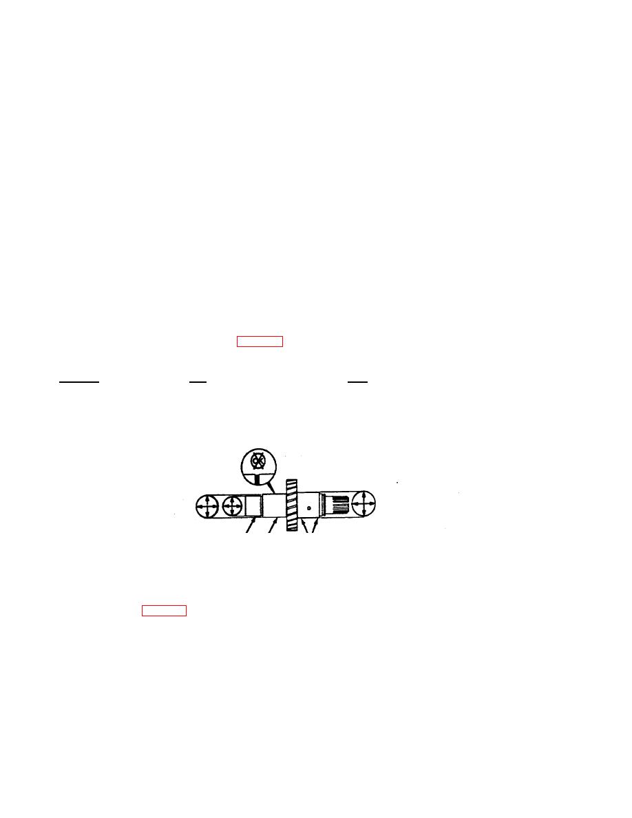
g. Check the shaft (5) for wear, chips or burrs. Measure the shaft outside
diameter at the locations shown in FIG. 3-6. Verify measurements are
within the following specifications:
Location
Min
Max
1
1.3810 in (35.077 mm)
1.3815 inch (35.090 mm)
2
1.5615 in (39.662 mm)
1.5620 inch (39.675 mm)
3
1.7480 in (44.399 mm)
1.7490 inch (44.425 mm)
FIGURE 3-6. Straight Shaft Measurement Locations.
NOTE
Only remove the gear from the shaft when the gear or the shaft must be replaced.
h. If the shaft (5, FIG. 3-5) measurements are not in specification or the
gear is damaged, replace as follows:
3-23
|
||
|
||


