
| Tweet |

Custom Search
|
|

|
||
 TM 55-1905-223-24-1
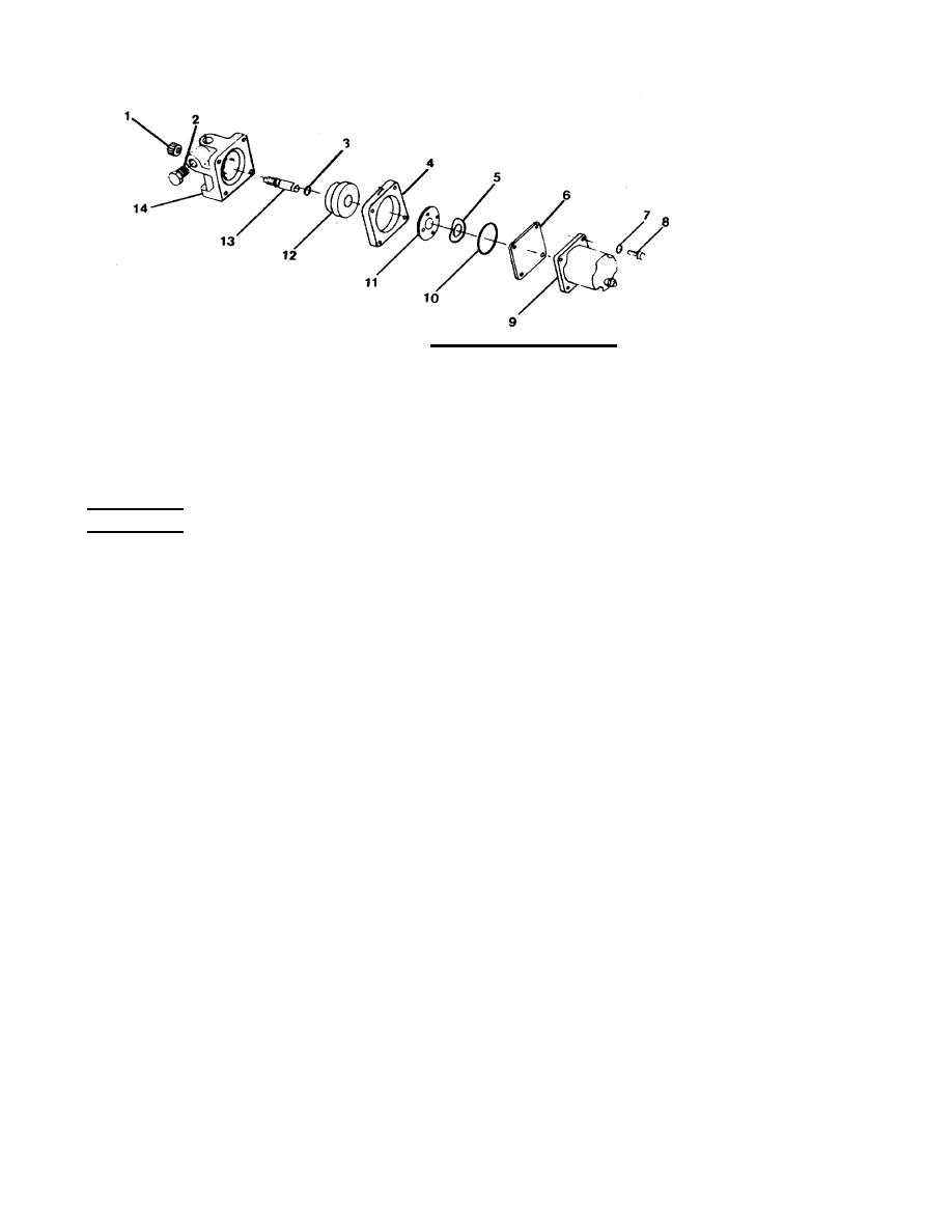
FIGURE 3-8. Shutdown Valve Assembly.
b. Inspect the actuator disk (12) for evidence of wear or other physical dama e. Replace as required.
g
c.
Inspect all other components for thread wear or other evidence of physical damage. Inspect the
actuator housing (4) for scoring and check orifices for cleanliness and freedom of fluid passage.
Replace any component found to be unserviceable.
ASSEMBLY
a. Lubricated preformed packing (3) with engine lube oil. Position preformed packing (3) on override shaft
(13).
b. Install actuator disk (12) on override shaft (13).
c. Insert override shaft (13) into valve body (14) with override shaft (13) through opening in back of valve
body.
d. Install override knob (1) on end of override shaft (13).
e. Position actuator housing (4) on valve body (14) with bolt holes aligned.
f. Insert valve disk (11) and spring tension washer (5) into bore of actuator housing (4).
g. Position preformed packing (10) on actuator housing (4).
h. Position access cover (6) on actuator housing (4) with bolt holes aligned.
3-33
|
||
|
||


