
| Tweet |

Custom Search
|
|

|
||
 TM 55-1905-223-24-1
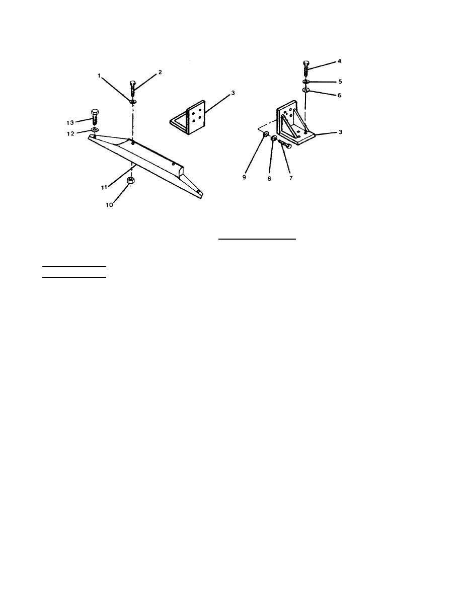
FIGURE 3-12. Engine Support Group.
REPLACEMENT
a. Position front engine mount (11) on engine frame wth bolt holes aligned.
i
b. Loosely install hexagon head capscrews (13) with lockwashers (12).
c.
Position rear engine supports (3) on engine with bolt holes aligned.
d. Loosely install hexagon head capscrews (7), with lockwashers (8) and flat washers (9).
e. Lower engine into position with front bolt holes aligned with bolt holes of front engine mount (11).
f. Loosely install hexagon head capscrews (2), lockwashers (1) and hex nuts (10).
g. Align bolt holes in rear engine supports (3) with bolt h les in engine frame.
o
h. Loosely install hexagon head capscrews (4), lockwashers (5) and flat washers (6).
i.
After all hexagon head capscrews are installed, tighten to 270 ft-lb (365 Nm).
3-50
|
||
|
||


