
| Tweet |

Custom Search
|
|

|
||
 TM 55-1905-223-24-1
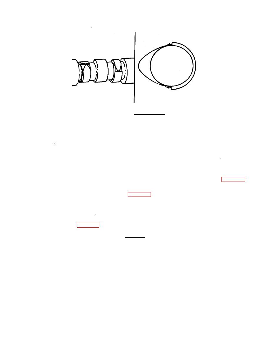
FIGURE 3-19. Camshaft Pilots.
(4) If necessary, rotate camshaft (9) until holes in gear (14) allow access to holes in retaining plate.
(5) Install lockplates (12) and hexagon head capscrews (13). Tighten capscrews (13) to 35 ft-lb (45
N m). Bend lockplates (12).
(6) Remove camshaft pilot from the rear of camshaft (9). Install gasket (8) and camshaft rear cover
(7). Install lockwashers (5) and hexagon head capscrews (6). Tighten to 30 ft-lb (40 N m).
(7) Repeat steps (1) through (6) for remaining camshaft if required.
(8) Attach a dial indicator gauge to the housing and check the camshaft end clearance (FIG. 3-18).
Verify end clearance is between 0.006 to 0.013 inch (0.15 to 0.33 mm) on both camshafts. If the
end clearance is not within the limits, check for foreign material or a piece of gasket material
between the shaft retaining plate (11, FIG. 3-17) and the block. If measurement is still out of
tolerance, evacuate to intermediate general support and check shaft retaining plate thickness.
(9) Replace front and rear camshaft covers using new gaskets. Tighten capscrews alternately and
evenly to 30 ft lb (40 N m).
b. Replace idler gears (2, FIG. 3-17).
CAUTION
The grooves in the thrust washers must be toward the
idler gears. Failure will result if the thrust washers are
installed wrong.
3-77
|
||
|
||


