
| Tweet |

Custom Search
|
|

|
||
 TM 55-1905-223-24-1
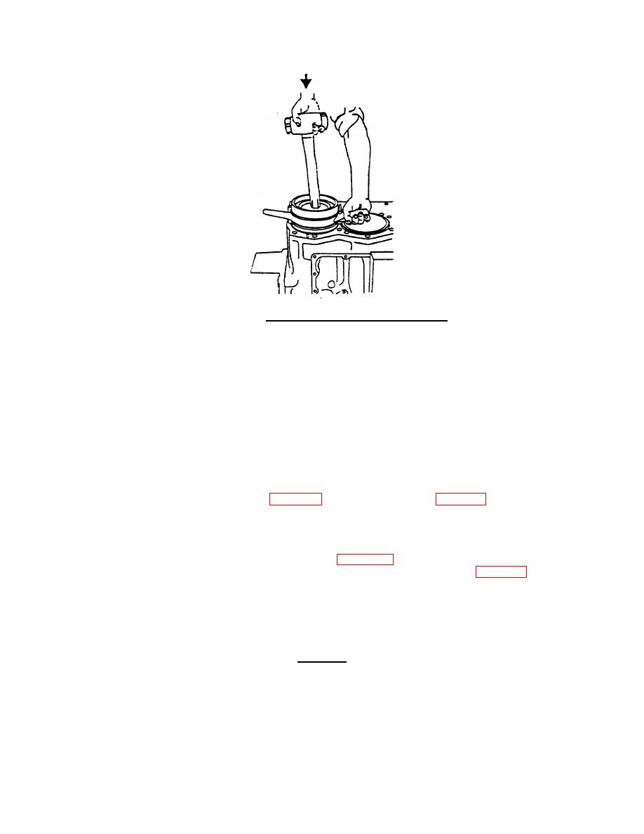
FIGURE 3-26. Piston and Connecting Rod Installation.
NOTE
After the piston and rod assemblies that share a
crankshaft journal are installed and the caps are pulled
to the rods, the crankshaft can be rotated. Rotating the
crankshaft so that the installed rods are on the bottom
will aid reaching the machine bolts. It is recommended
that the four rods that are connected to the two
crankshaft rod journals that have the same centerline be
installed, then the crankshaft rotated to the bottom.
c. Measure connecting rod bolt stretch.
(1) Tighten connecting rod bolts (3, FIG. 3-22) using the procedure in Table 3-5. Apply torque to both
bolts.
(2) Loosen both bolts (3).
(3) Position rod bolt checking fixture on rod bolt (FIG. 3-27). Ensure the fixture anvil is centered in
hole of the rod bolt and the figure contacts the head of the bolt as shown in FIG. 3-27.
(4) Adjust the fixture indicator to the 0.050 inch mark. Ensure that there is a minimum of 0.030 travel
remaining.
(5) Tighten indicator lock to maintain reading. Record reading as "First Bolt Zero."
CAUTION
Do not adjust indicator.
3-88
|
||
|
||


