
| Tweet |

Custom Search
|
|

|
||
 TM 55-1905-223-24-1
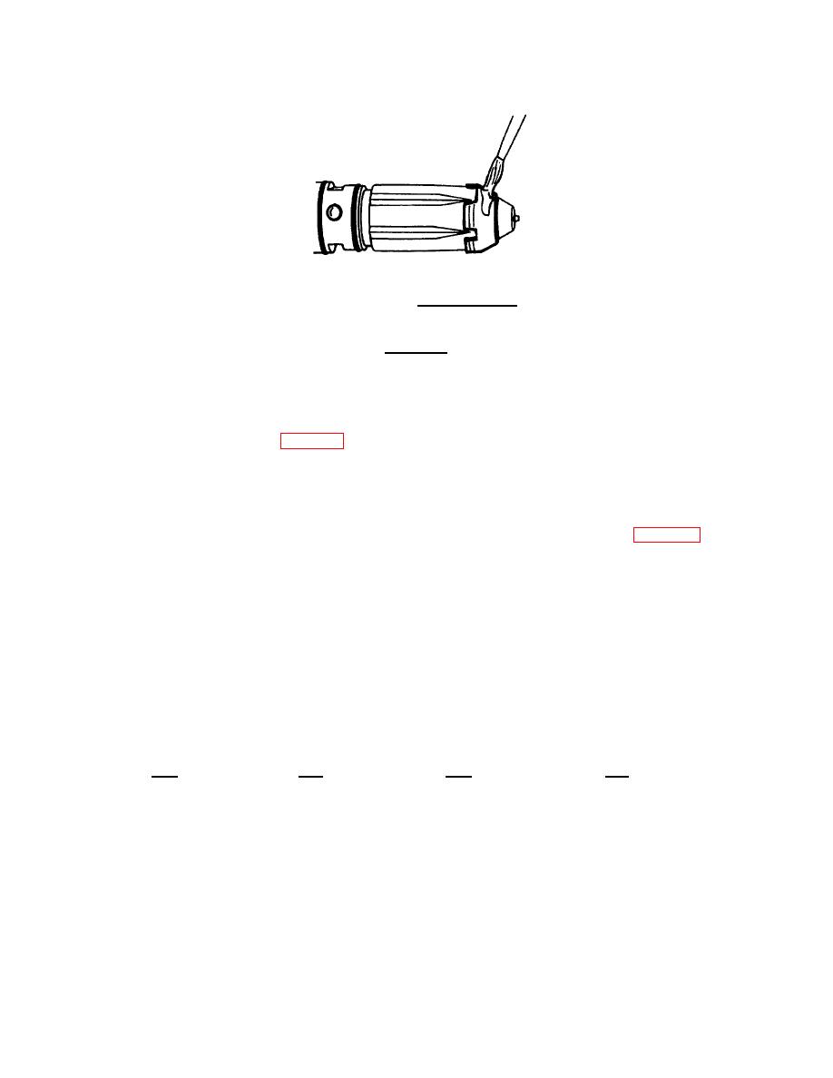
FIGURE 4-16.
Dummy Injector.
CAUTION
Support the cylinder head to prevent damage to the injector tip
that protrudes from the combustion face, and to allow the
injector to touch the seat correctly.
(d) Install the injector (3, FIG. 4-17) in the cylinder head (4).
(e) Install injector holddown clamp (2).
(f) Install capscrews (1). Tighten screws to 145 in-lb (16 N-m).
(g) Turn cylinder head (4) over. Use a gauge block to measure injector protrusion (FIG. 4-18).
Verify injector protrusion is between 0.090 inch (2.29 mm) and 0.110 inch (2.79 mm).
(h) If protrusion is not within specifications, use an oversized sealing ring. Sealing rings are available
in various sizes as shown below.
NOTE
The 0.0135 to 0.0165 inch (0.343 to 0.419 mm) is the
standard sealing ring.
Wall Thickness
Protrusion
(Min/Max)
Change
Inch
mm
Inch
mm
0.0135/0.0165
0.343/0.419
0.000
0.000
0.0185/0.0215
0.470/0.546
0.010
0.25
0.0235/0.0265
0.597/0.673
0.020
0.51
0.0285/0.0315
0.724/0.800
0.030
0.76
4-17
|
||
|
||


