
| Tweet |

Custom Search
|
|

|
||
 TM 55-1905-223-24-1
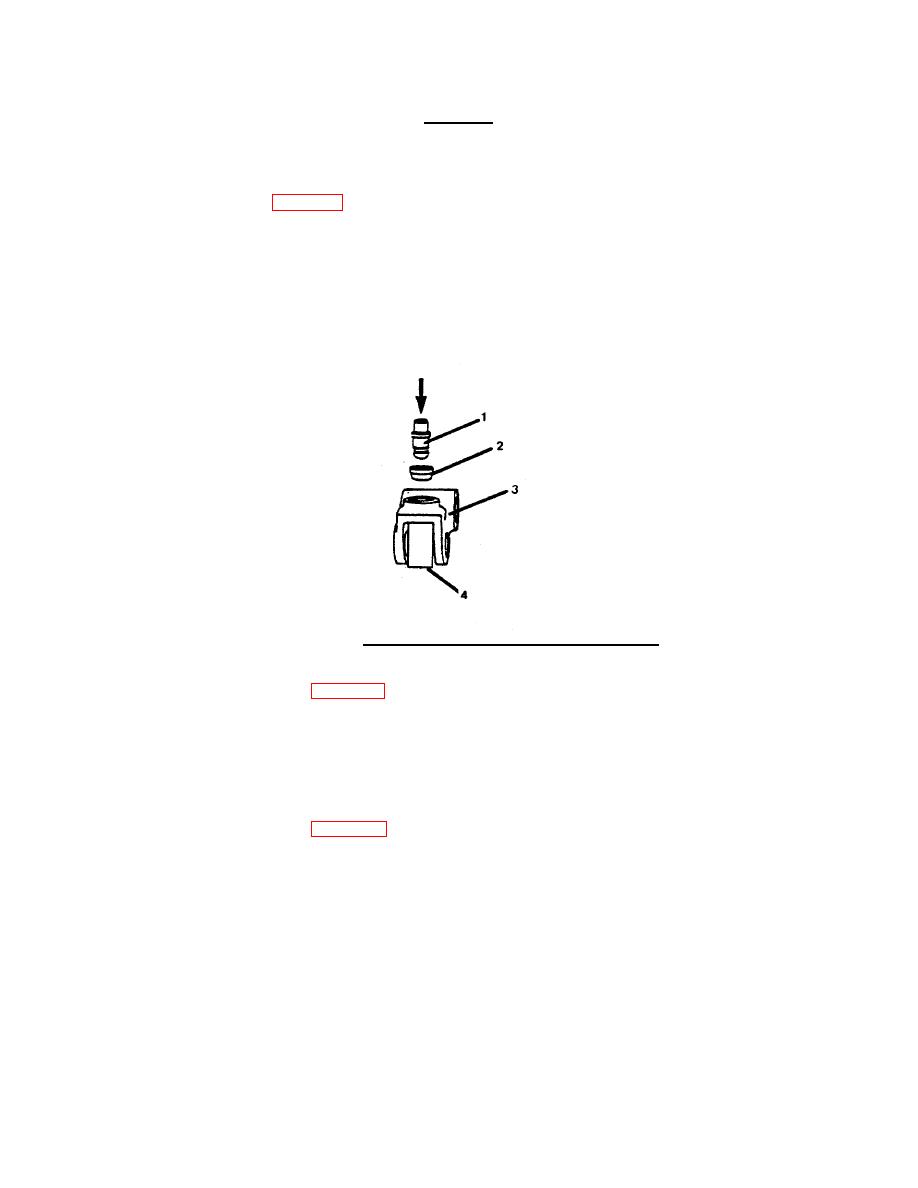
CAUTION
Failure to use roller for support can cause cracks
in the cam follower.
(5) Position roller (4, FIG. 4-41) in cam follower (3) when installing socket (2).
(6) Use a brass drift or used push rod (1) and an arbor press to install socket (2). Ensure socket touches
the bottom of the bore in the cam follower (3).
e. Check for surface imperfections by magnetic inspection. Apply a coil magnetization amperage of 300
to 500 with residual Magnaglo. Demagnetize all serviceable parts after inspection. Remove any burrs
from the bore of the lever with 240-grit sandpaper.
FIGURE 4-41. Cup Plug Installation in Cam Follower Shaft.
f. Check the cam roller (5, FIG. 4-39) width, outside diameter and bore inside diameter. Verify they are
within the following specifications.
Width valve roller
0.672 inch (17.07 mm) maximum
Width injector roller
0.993 inch (25.22 mm) maximum
Outside diameter
1.625 inch (41.28 mm) maximum
Inside diameter
0.755 inch (19.18 mm) maximum
g. Roll pushrods (3 and 4, FIG. 4-39) across a level surface to check for straightness. Check both ends
of rod for scratches and abrasions. Replace as required.
h. Replace defective parts as required.
4-34
|
||
|
||


