
| Tweet |

Custom Search
|
|

|
||
 TM 55-1905-223-24-1
(3) Replace the damper if variations of 0.010 inch (0.25 mm) or more are found or if the thickness
exceeds 2.574 inches (65.38 mm).
(4) Inspect all other mounting components for physical damage or wear. Replace as required.
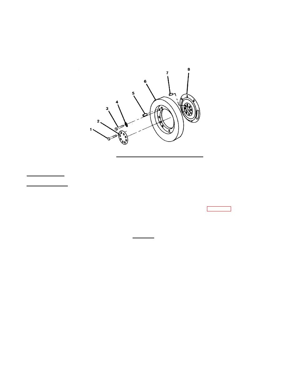
FIGURE 4-43. Vibration Damper Mounting Components.
c. Repair consists of replacement of defective parts.
REPLACEMENT
a. Wipe the crankshaft and damper mating surfaces with a clean dry cloth. Ensure surfaces are free of
nicks and burrs.
b. Install roll pins in the front nose of the crankshaft and adapter face (7, FIG. 4-43), if they were
removed.
c. Install two nine-inch guide studs 180 degrees apart in the capscrew holes of the crankshaft.
CAUTION
The crankshaft adapter must be aligned correctly with the
crankshaft. Incorrect alignment will cause the valve and
injector adjustment marks on the vibration damper to be in
the wrong direction.
d. Align the roll pin with the receiving hole and position the adapter (8) over the guide studs to the
crankshaft. Install spacer (2).
e. Lubricate threads and heads of bolts (1) with clean engine lube oil. Install four bolts (1) 90 degrees
apart. Tighten bolts alternately and evenly to pull adapter (8) on the crankshaft. Ensure adapter is
flat against crankshaft.
4-39
|
||
|
||


