
| Tweet |

Custom Search
|
|

|
||
 TM 55-1905-223-24-1
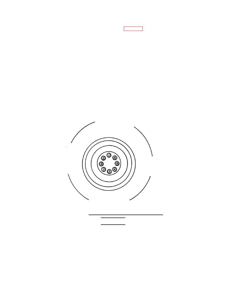
f. Install remaining bolts (1). Using the sequence in FIG. 4-44, torque bolts to 160 ft-lb (220 N m).
Advance bolts to 290 ft-lb (395 N ). Apply final torque of 410 ft-lb (555 N ).
m
m
CAUTION
Dampers are available with standard and high viscosity fluid
inside. If the damper has been replaced, verify the correct
damper is installed.
The vibration damper must be aligned correctly with the
crankshaft adapter. Incorrect alignment will cause the
valve and injector adjustment marks on the damper to be in
the wrong position.
The vibration damper is heavy. To avoid personal injury or
equipment damage, use a lifting sling or get assistance when
lifting the vibration damper.
g. Position the vibration damper (6) over the guide studs, engaging the adapter roll pin (7) and damper
receiving hole.
FIGURE 4-44. Tightening Sequence for Crankshaft Adapter.
WARNING
The capscrews (3) must be SAE grade 8. The washers (4) must
be hardened. If the wrong parts are used, the capscrews
could fail, allowing the damper to become loose and cause
personal injury.
h. Lubricate the washer (4) faces and capscrews (3) threads with clean engine lubricating oil. Torque the
capscrews (3) alternately and evenly to 155 ft-lb (210 N m).
i. Check the vibration damper for eccentricity and wobble as follows.
4-40
|
||
|
||


