
| Tweet |

Custom Search
|
|

|
||
 TM 55-1905-223-24-1
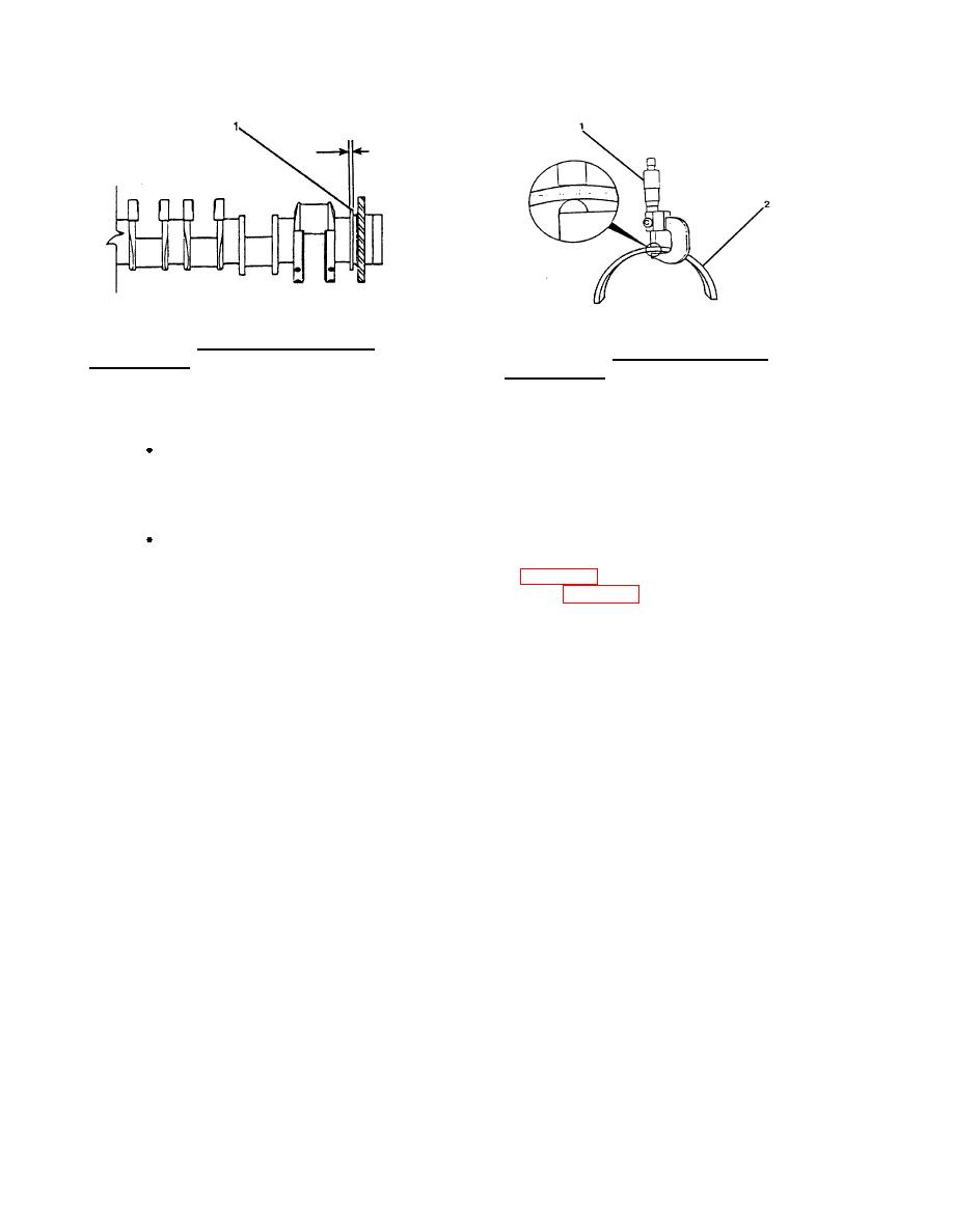
FIGURE 4-52. Crankshaft Thrust Flange
FIGURE 4-53. Bearing Shell (Sleeve)
Measurement.
Measurement.
NOTE
Do not scrape the bearing shells, or they will have to be lap filed, which increases the
oil clearances. A properly fitted bearing will appear dull gray after a reasonable period
of service, indicating it is running on an oil film. Bright spots indicate a metal-to-metal
contact and black spots indicate an excessive clearance.
Reground crankshafts or those used with undersize rod and main bearings and/or
oversized thrust rings should be marked so the correct bearing shells and thrust rings
can be installed in proper position. Markings (2, FIG. 4-54) for rod and main bearings
are on the front counterweight (1). Thrust ring size (2, FIG. 4-55), and location are on
the rear counterweight.
g.
Install the crankshaft gear if removed.
(1)
Install the key in the shaft.
(2)
Heat the gear in a preheated oven at 400 (205 ) for a minimum of one hour.
F
C
(3)
Lubricate the flange with high pressure grease. Install the gear onto the shaft.
4-47
|
||
|
||


