
| Tweet |

Custom Search
|
|

|
||
 TM 55-1905-223-24-1
CAUTION
Use a vise with brass jaws to hold the rod. Notches, scratches, or dents in the rod will cause engine
failure.
The number on the connecting cap must be the same as the number on the rod cap.
Never
assemble a new cap to an old rod or an old cap to a new rod.
(7)
Lubricate the connecting rod capscrews (3, FIG. 4-66) with clean engine lube oil.
(8) Assemble the rod (1), cap (2), washers (4) and capscrews (3).
Tighten capscrews in the following
sequence:
Step
Torque Value
1
80 ft-lb (108 N )
m
2
160 ft-lb (217 N )
m
3
240 ft-lb (326 N )
m
4
Loosen both capscrews
5
80 ft-lb (108 N )
m
6
160 ft-lb (217 N )
m
7
240 ft-lb (326 N )
m
(9)
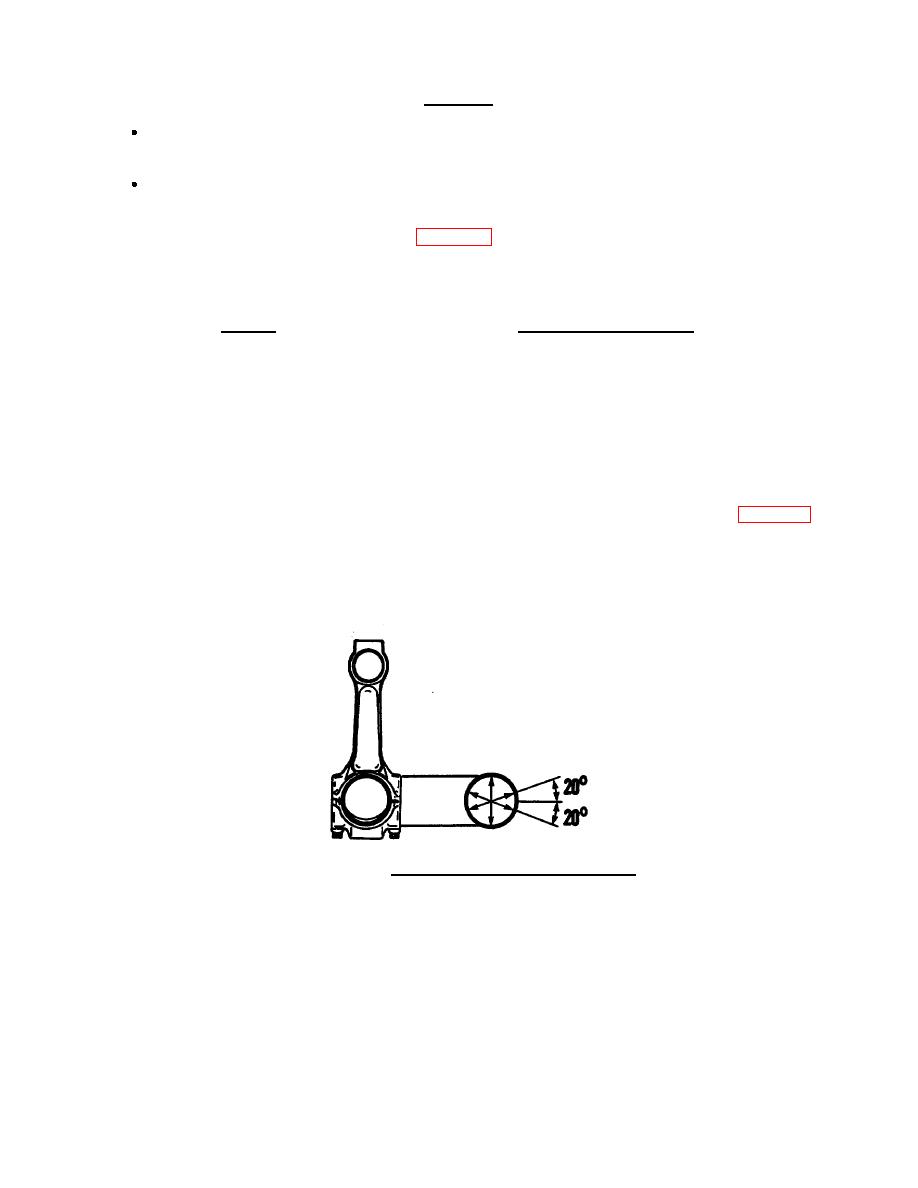
Use a dial bore indicator. Measure the inner diameter of the connecting rod bearing bore. Measure at 90
degrees from the parting line and within a 20-degree arc from each side of the parting line (FIG. 4-68).
FIGURE 4-68. Connecting Rod Bore Measurement.
(10) Verify all three measurements are between 4.5017 inch (114.343 mm) and 4.5027 inch (114.369 mm).
Replace rod if any measurement is not to specification.
(11) Set up magnaglo tester for head shot method using instructions provided on tester. Apply bath solution
to area being checked. Apply head shot amperage of 1500 ampere dc or rectified ac. Check for cracks.
4-71
|
||
|
||


