
| Tweet |

Custom Search
|
|

|
||
 TM 55-1905-223-24-1
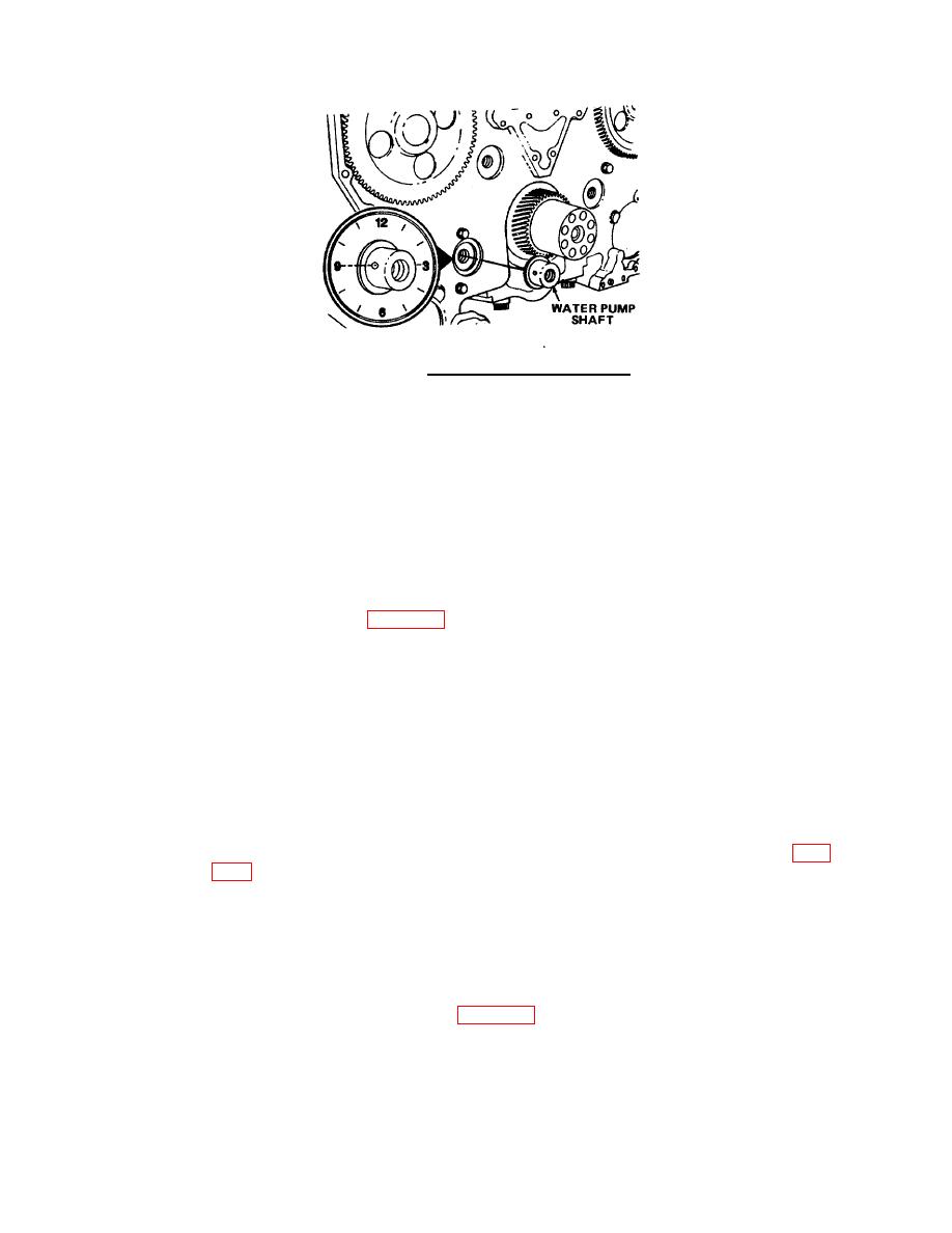
FIGURE 4-76. Water Pump Shaft Alignment.
(1) Remove six capscrews (24).
(2) Remove upper bearing retaining plate (25).
e.
Remove engine lifting brackets.
(1) Remove machine bolts (71) and washers (70).
(2) Remove four engine lifting brackets (69).
f.
Remove cylinder liner.
(1) Loosen set screws (1, FIG. 4-77) on cylinder liner puller.
(2) Turn feet (2) until the curved side is turned from the center.
(3) Move holding pins (3) to last hole.
NOTE
The puller feet must not touch the top of the liner.
The puller arms must be
positioned firmly on the bottom of the liner.
(4) Install puller in cylinder liner.
(5) Turn puller screw (4) until liner loosens in block. Remove tool and cylinder liner (8, FIG.
(6) Remove shims (2 through 7), preformed packing (10 and 11), plain seal (12), and special ring
(9).
g.
Remove expansion plugs, expansion shields, pipe plugs and dowels.
(1) Use a drill, metal screw and slide hammer and hook from the light duty puller kit (FIG. 4-
78) to remove expansion plug (15, FIG. 4-75) and expansion shields (14).
4-87
|
||
|
||


