
| Tweet |

Custom Search
|
|

|
||
 TM 55-1905-223-24-1
o.
Inspect idler shafts (47 and 50).
(1) Check idler shafts for cracks, bends and other damage.
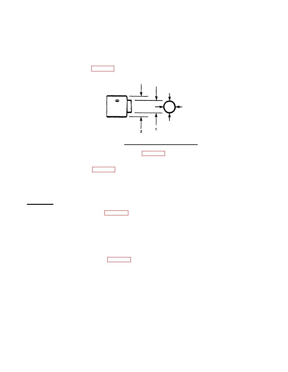
(2) Measure camshaft idler shaft (47) outside diameter.
(3) Verify outside diameter is between 0.9995 and 1.000 inch (25.397 and 25.400 mm) at
location 1 in FIG. 4-86a. Verify outside diameter is between 1.8720 and 1.8740 inch
(47.549 and 47.600 mm) at location 2.
FIGURE 4-86a. Camshaft Idler Shaft Measurement.
(4) Measure water pump idler shaft (50, FIG. 4-75) outside diameter.
(5) Verify outside diameter is between 1.6995 and 1.7000 inch (43.167 and 43.180 mm) at
location 1 in FIG. 4-86a. Verify outside diameter is between 1.8720 and 1.8740 inch
(47.549 and 47.600 mm) at location 2.
(6) Replace idler shafts if damaged or not to specifications.
ASSEMBLY
a.
Install camshaft bushing (44, FIG. 4-75).
NOTE
Steps (1), (2), and (3) are for installing bushings in bores that require two bushings.
Steps (4), (5), and (6) are for installing single bushings in the LB Front and RB
Rear bores.
(1) Position bushing (2, FIG. 4-87) so that clinch joint (3) is pointed toward the cylinder head
surface of the block and the elongated hole (4) is on the side nearest to the use of the block.
4-98
|
||
|
||


