
| Tweet |

Custom Search
|
|

|
||
 TM 55-1905-223-24-18-2
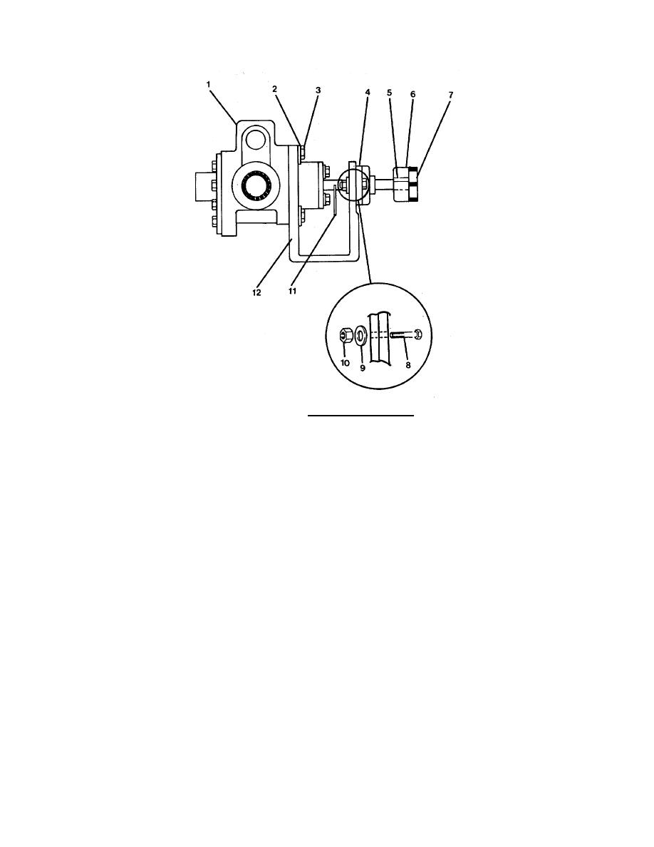
ASSEMBLY
a. Position pump (1) on shaft bracket (12).
b. Secure pump to shaft bracket with four lockwashers (2) and hex head capscrews (3).
c. Install outboard bearing (4) on shaft (11) and mounting screw holes aligned.
d. Secure outboard bearing to shaft bracket with two hex head capscrews (8),
lockwashers (9) and hex plain nuts (10).
e. Install machine key (5) on shaft (11).
f. Install half coupling (6).
g. Install spider coupling (7) on half coupling.
h. Replace appropriate rotary pump unit as specified in paragraph 2-101, 2-104, or 2-107.
3-397
|
||
|
||


