
| Tweet |

Custom Search
|
|

|
||
 TM 55-1905-223-24-3
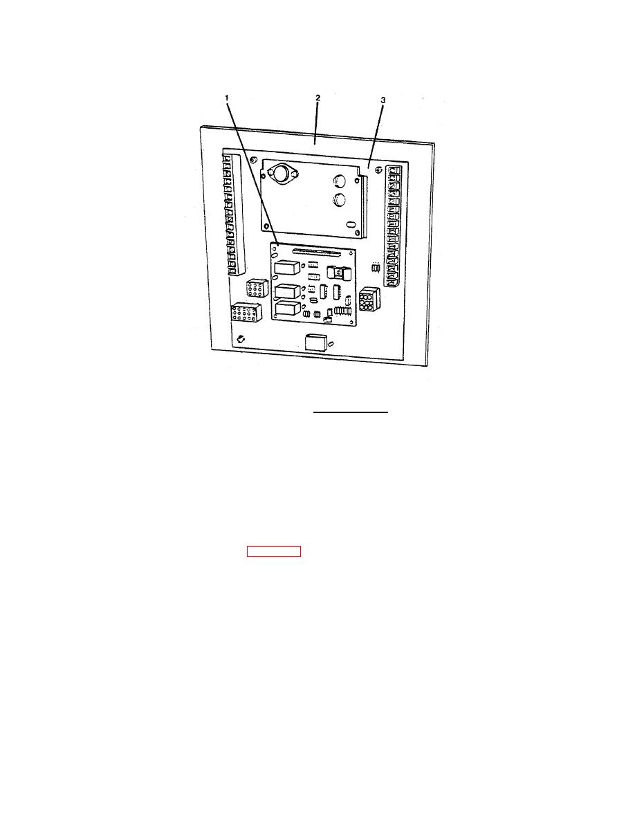
FIGURE 2-7. Terminal Board.
(b) Remove the four machine screws and four lockwashers securing the overspeed switch (1) to
the terminal board (3).
(c) Remove the overspeed switch (1) from the terminal board (3).
(d) Position the new overspeed switch (1) on the terminal board (3) and install four screws and
lockwashers.
(e) Connect wiring connections to terminal strip. Remove tags.
(2) Replace the governor control (2, Figure 2-7) as follows:
(a) Disconnect and tag all wiring connections to the governor control (2).
(b) Remove the four machine screws and four lockwashers securing the governor control (2) to the
terminal board (3).
(c) Remove the governor control (2) from the terminal board (3).
(d) Position the new governor control (2) on the terminal board (3) and install four screws and
lockwashers.
2-62
|
||
|
||


