
| Tweet |

Custom Search
|
|

|
||
 TM 55-1905-223-24-3
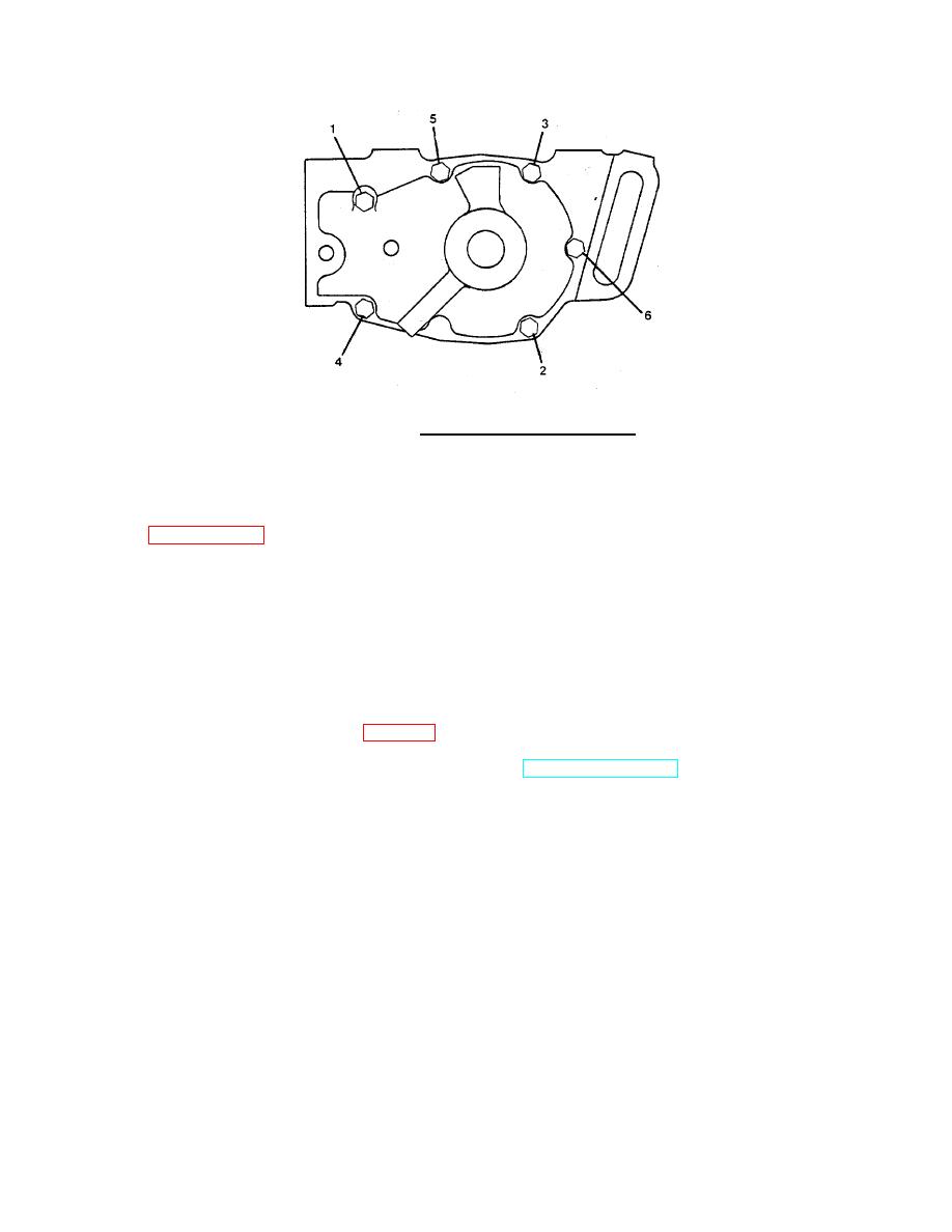
FIGURE 2-16. Water Pump Torque Sequence.
e. Tighten the capscrews (3) and the screw (4) to the 35 ft-lb (47.4 N ) torque.
m
f.
Install the preform packing and transfer tube to the top of the body (10) with the rim-clenching clamp
g. Install the adjusting device (20) in the adjustment slot in the water pump body (10) and install
lockwasher (12) and nut (11). Do not tighten the nut until the V-belt (25) has been installed.
h. Install the capscrew (13) into the body (10). Turn the capscrew only a few turns.
i.
Install a new V-belt (25) and adjust. Refer to the Adjustment steps in this procedure.
j.
Install the belt guard (21) with capscrews (22), lockwashers (23) and flat washers (24).
k.
Fill the cooling system. Refer to Table 2-1, Item 24.
i.
Remove tags, turn on electrical power, run the engine (TM 55-1905-223-10), and check for leaks.
Correct as required.
2-90
|
||
|
||


