
| Tweet |

Custom Search
|
|

|
||
 TM 55-1905-223-24-3
g. Disconnect nonmetallic hose assembly (6), pipe-to-tube elbow (7), and tube-to-hose elbow (13) and
remove.
h. Remove straight pipe-to-hose adapter (8) from pressure switch (9).
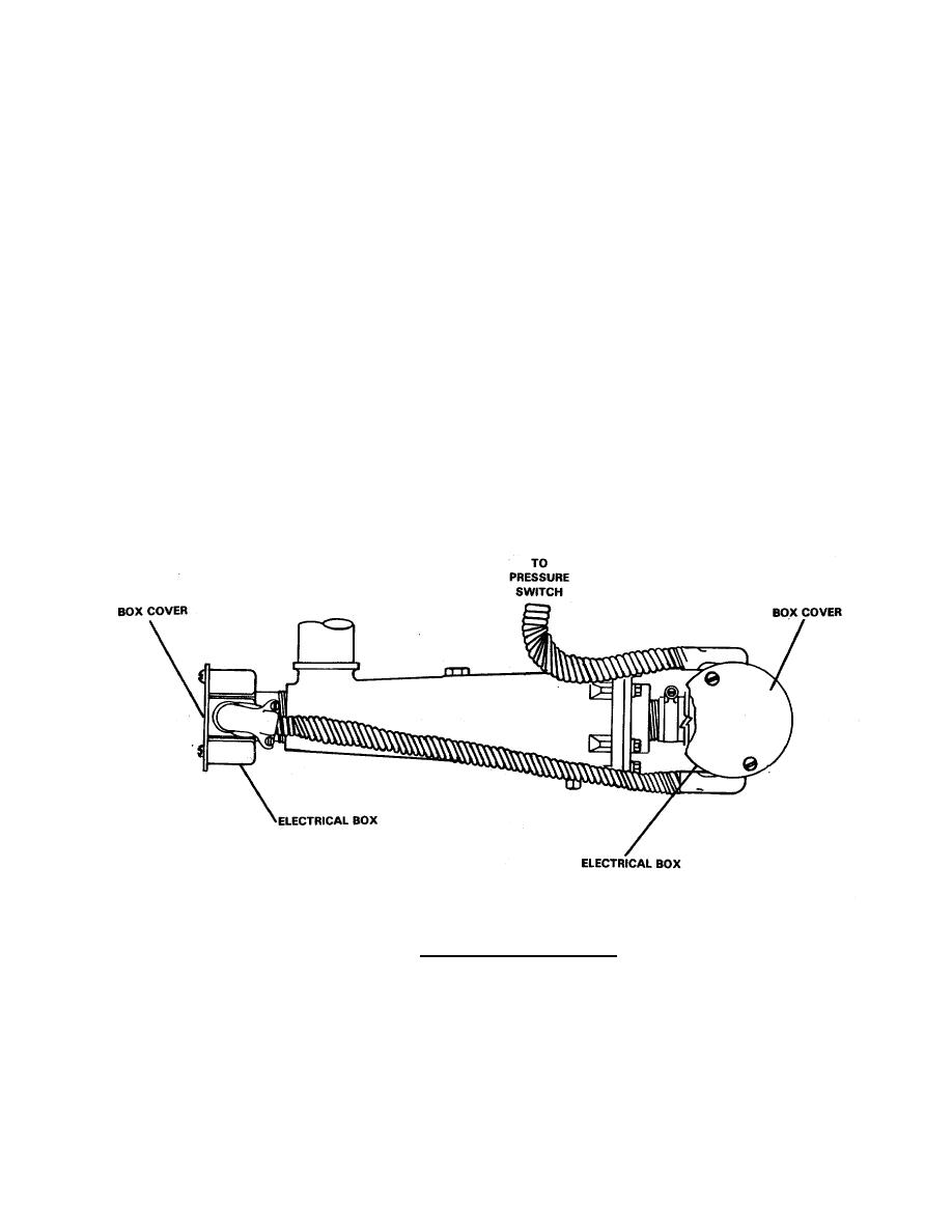
NOTE
The electrical boxes and cabling are removed with the engine coolant heater
(28). Figure 2-20 shows location of electrical boxes for reference only.
i.
Tag and disconnect electrical wiring from pressure switch (9).
j.
Remove hexagon head capscrews (10), lockwashers (11), and plain hexagon nuts (12) securing
pressure switch (9) to angle bracket (27).
k.
Remove pressure switch (9).
l.
Remove four hexagon head capscrews (22), lockwashers (21), and plain hexagon nuts (20) securing
engine coolant heater (28) to angle bracket (27).
m. Remove engine coolant heater (28).
n. Remove pipe-to-hose elbow (29) and straight pipe-to-hose adapter (19) from engine coolant heater
(28).
Figure 2-20. Location of Electrical Boxes.
2-99
|
||
|
||


