
| Tweet |

Custom Search
|
|

|
||
 TM 55-1905-223-24-3
NOTE
Both valves are closed when both rocker levers are loose and can be moved
from side to side. If both valves are not closed, rotate the accessory drive one
complete revolution; align the "A" mark with the pointer again.
CAUTION
To prevent damage to the indicator or to avoid getting an incorrect reading, install
the dial indicator extension so that it clears the rocker lever. See Figure 2-32.
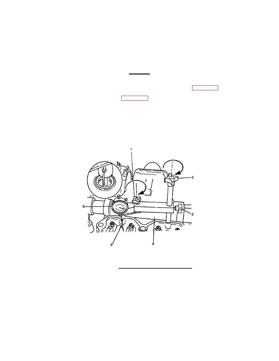
(c)
Install the dial indicator (6, Figure 2-32) and the support (4) from the Injector Adjustment
Kit so that the stem (5) of the dial indicator is on top of the injector plunger flange on
cylinder No. 3.
(d)
Securely tighten the thumbscrew (1) and the holddown screw (2) in place.
(e)
Loosen the thumbscrew (3) and lower the indicator against the injector plungerflange until
the stem (5) is fully compressed.
FIGURE 2-32. Installing Dial Indicator and Support.
2-119
|
||
|
||


