
| Tweet |

Custom Search
|
|

|
||
 TM 55-1905-223-24-3
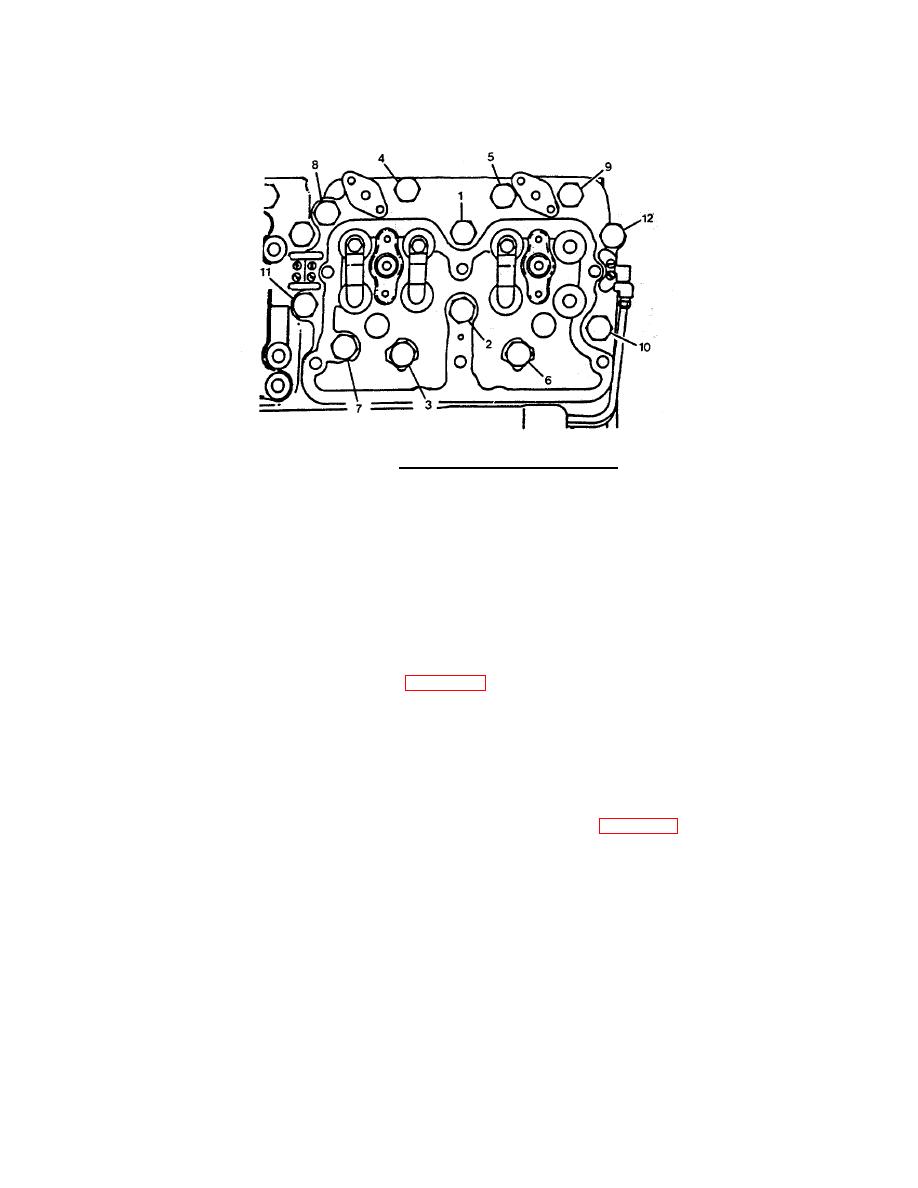
FIGURE 2-55. Cylinder Head Torque Sequence.
(4)
Use light finger pressure to hold the crosshead (3) in position, and tighten the adjusting screw (1) until
it touches the top of the valve stem.
NOTE
When a torque wrench adapter is used, tighten the lock nut (2) to 25 ft-lb (33.8 N m)
torque. If torque wrench adapter is not used, tighten to 30 ft-lb (41 N m) torque.
(5)
Measure the clearance (1 and 2, Figure 2-56) between the crosshead and the valve spring retainer.
The clearance must be a minimum of 0.025 inch (0.65 mm).
NOTE
The injector push rods are larger in diameter than the valve push rods.
l.
Install the push rods in the cylinder head as follows:
(1)
Use clean engine oil to lubricate the ball end of the push rods(1, Figure 2-52).
(2)
Install the push rods in the corresponding numbered location.
2-150
|
||
|
||


