
| Tweet |

Custom Search
|
|

|
||
 TM 55-1905-223-24-3
(d) Shut down generator and turn electrical power OFF and tag (TM 55-1905-223-10). Remove the
separate 12 volt battery and reconnect all leads to the voltage regulator and externaconnections
l
that were removed for test purposes.
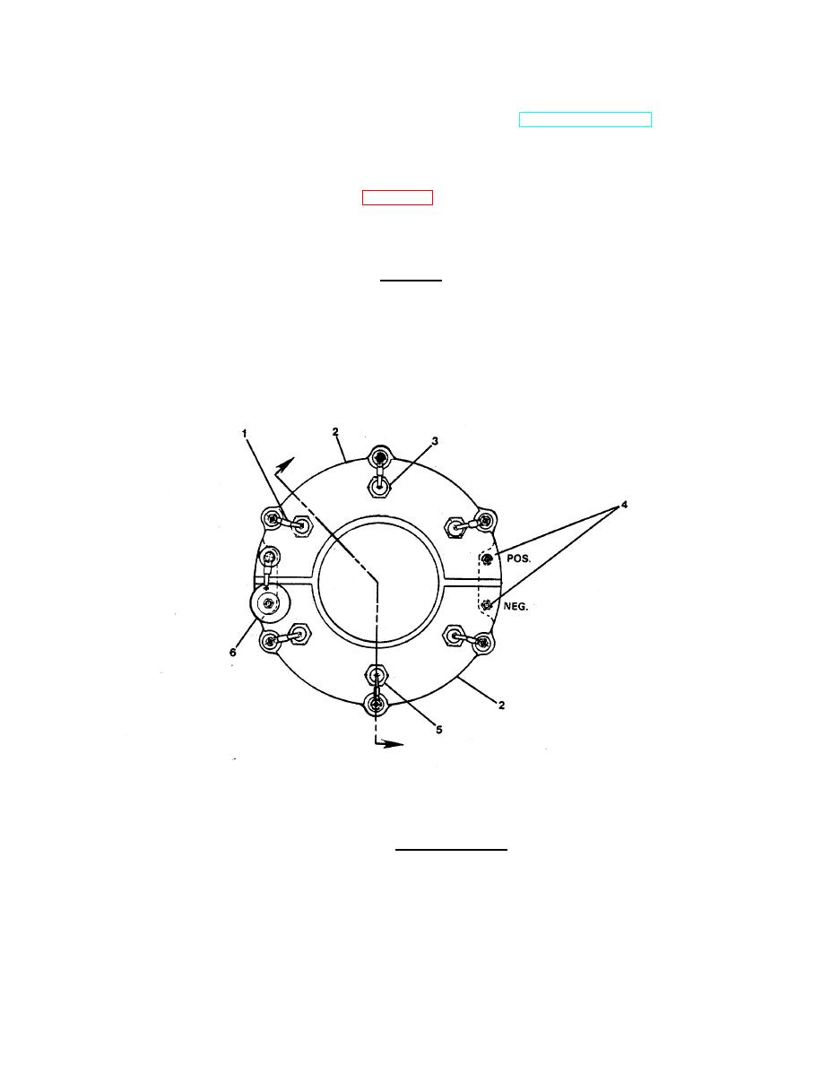
(4) With the generator set shut down and cool, and electrical power OFF, check the rectifier
semiconductors. The rectifier assembly (Figure 3-6) is split into two plates, positive and negative, and
the main rotor is connected across these plates. The positive plate has three positive semiconductors,
and the negative plate has three negative semiconductors.
CAUTION
Ensure that the correct polarity of the semiconductors is fitted to
each respective plate.
FIGURE 3-6. Rectifier Assembly.
3-20
|
||
|
||


