
| Tweet |

Custom Search
|
|

|
||
 TM 55-1905-223-24-3
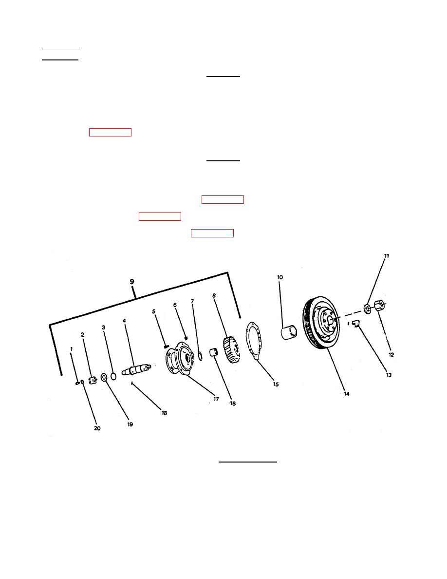
REMOVAL
CAUTION
The timing marks on the accessory drive gear and the camshaft gear must be
aligned so that the valve and injector set marks on the accessory drive pulley
show the correct adjustment position.
a. Rotate the crankshaft until the "A" mark on the accessory drive is aligned with the pointer on the gear
cover (Figure 3-30).
CAUTION
The gear cover will be damaged if the puller capscrews extend beyond the rear
face of the accessory drive pulley.
b. Remove the self-locking hexagon nut (12, Figure 3-31) and flat washer (11).
c.
Remove the pulley (14, Figure 3-31), rubber strip (13) with standard gear puller.
d. Remove the inspection hole pipe plug (Figure 3-32) in the gear cover.
FIGURE 3-30. Alignment Pointer.
3-66
|
||
|
||


