
| Tweet |

Custom Search
|
|

|
||
 TM 55-1905-223-24-3
CAUTION
Do not allow dirt or gasket material to enter oil passages on the pump. Bearing
damage will result.
d.
Remove two assembled washer machine screws (17) and remove access cover (16) and gasket (15). Discard
gasket.
e.
Using solvent, clean pump and cylinder block gasket surfaces, dry with compressed air.
f.
Inspect gears (25, 27 and 34) for freedom of rotation.
g. Inspect gears (25, 27 and 34) for cracked or broken teeth. Replace in REPAIR procedure if cracked or
broken teeth are observed.
h.
Inspect bushings (28 and 24) for excessive wear or discoloration due to overheating or seizure to the shafts.
Replace if necessary in REPAIR procedure.
i.
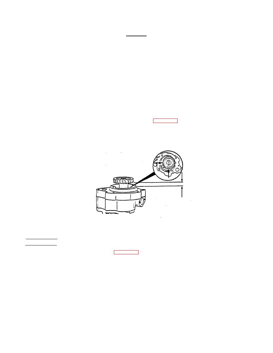
Use depth verniers to measure drive shaft (30) end clearance (Figure 3-48) in two locations 90 part. Drive shaft
end clearance should be as follows:
Minimum - 0.002 inch (0.05 mm)
Maximum - 0.005 inch (0.13 mm)
FIGURE 3-48. Drive Shaft End Clearance.
DISASSEMBLY
a.
Remove assembled washer capscrews (21, Figure 3-47) securing cover (23) to pump body (31). Tap cover (23)
lightly with rubber hammer to help remove cover (23) from dowels (8) in the body (31). Remove cover.
b.
Remove the idler gear (25) from shaft (26).
c.
Using gear puller P/N 3375082 to remove drive gear P/N 143190 or gear puller P/N 3375083 to remove drive gear
P/N 125988, remove drive gear (27) from drive shaft (30) and drive gear (34).
3-93
|
||
|
||


