
| Tweet |

Custom Search
|
|

|
||
 TM 55-1905-223-24-3
Table 3-7.
Allowable Total Indicator Reading (TIR)
Flywheel Housing Bore and Face
Bore Diameter
Bore Location Tolerance
SAE
No.
(mm)
in
(mm)
in
00
(787.40 to 787.64)
31.000 to 31.010
(0.30)
0.012 TIR
0
(647.70 to 647.95)
25.500 to 25.510
(0.25)
0.010 TIR
1/2
(584.00 to 584.20)
23.000 to 23.008
(0.25)
0.010 TIR
1
(534.27 to 534.40)
20.125 to 20.130
(0.20)
0.008 TIR
2
(447.68 to 447.80)
17.625 to 17.630
(0.20)
0.008 TIR
3
(409.58 to 409.70)
16.125 to 16.130
(0.20)
0.008 TIR
(k)
If the bore alignment does not meet the specification, loosen the housing capscrews.
Tighten the capscrews again, and measure the bore alignment again.
(l)
If the alignment is not within specifications and the bore is round, the housing can be
shifted. Refer to paragraph 4-15.
(m) If the alignment is not within specifications and the bore is not round, the housing must
be replaced.
(5)
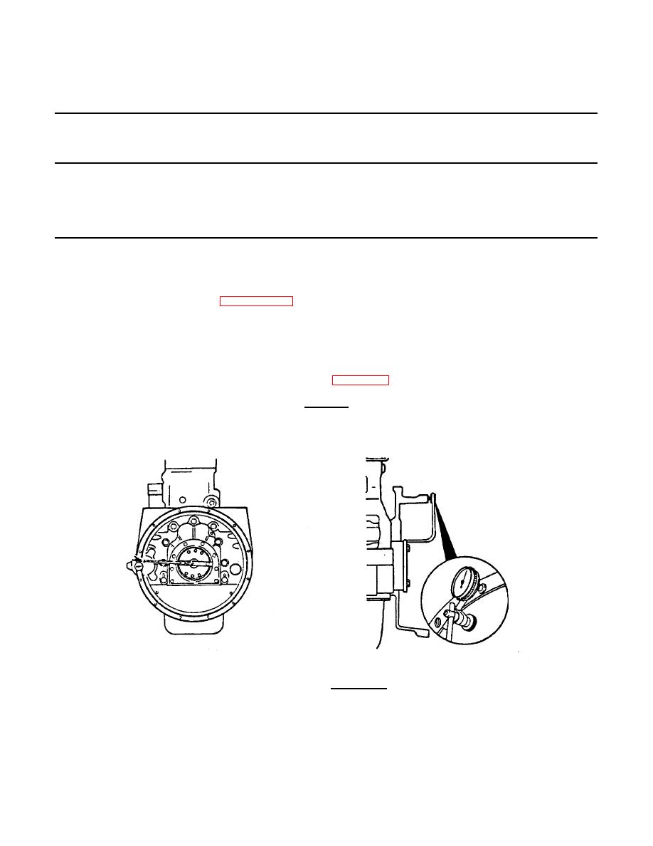
Measure the flywheel housing face alignment as follows:
(a)
Install the dial indicator as shown in Figure 3-73 .
CAUTION
The tip of the gauge must not enter the capscrew holes or the gauge will be damaged.
FIGURE 3-73. Dial Indicator.
3-121
|
||
|
||


