
| Tweet |

Custom Search
|
|

|
||
 TM 55-1905-223-24-3
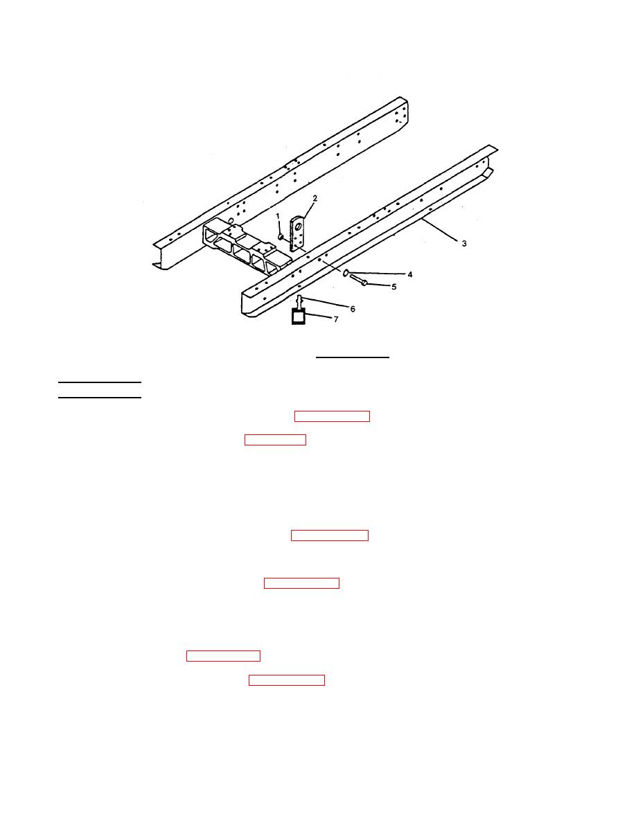
FIGURE 3-84. Subbase Group.
REPLACEMENT
a. Install new resilient mounts (7). Refer to paragraph 3-12.
b. Install the lifting padeyes (2, Figure 3-84) with capscrews (5), lockwashers (4), and nuts (1)-to the
subbase (3).
c. Attach the lifting fixture to each lifting pad eye (2) and lower the subbase (3) onto the six resilient
mounts (7).
NOTE
Adjust the mounts as described in paragraph 3-12 while positioning the subbase.
d. Install the nut on each of the six isolator mount studs.
(1) Install the resilient mount bolts (paragraph 3-12).
(2) Tighten the center bolt/nut on each resilient mount (7) to 120 ft-lb (160 N m) torque.
e. Remove the lifting fixture.
f. Install the engine (paragraph 3-13A).
g. Install the generator assembly (paragraph 3-13).
3-139
|
||
|
||


