
| Tweet |

Custom Search
|
|

|
||
 TM 55-1905-223-24-3
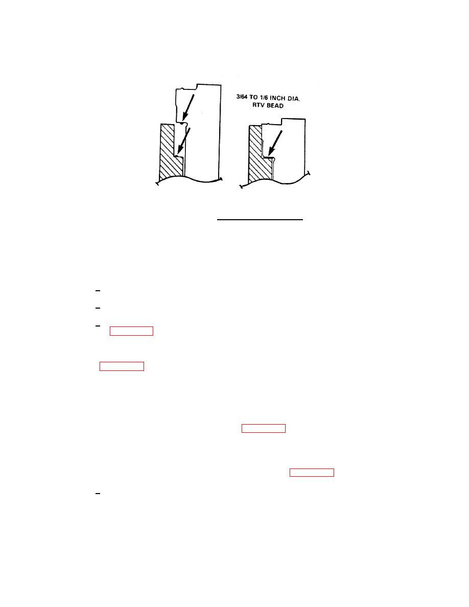
FIGURE 4-52. Applying Sealant to Liner.
(e) Use the cylinder liner driver and a leather mallet to drive the flange of the liner against the
counterbore ledge.
(f) Check the protrusion of the cylinder liner as follows:
1
Install the cylinder liner clamp set.
2
Tighten the capscrews to 50 ft-lb (67 N ) torque. Do not damage the liner bead.
m
3
Use the gauge block to measure the liner protrusion at four points 90 degrees apart
mm).
(g) Use a feeler gauge to measure the clearance between the liner and the lower liner bore
NOTE
The clamp set uses two cylinder head capscrews. The clamps
must be installed 180 degrees from each other to apply equal
amounts of pressure on the liner (Figure 4-53).
If the liner protrusion is below the specifications, liner s ims
h
might be required.
(h) Measure the liner bore for out of roundness as follows: (Figure 4-55)
1
Measure at points "C", "D", "E", "F", and "G".
4-106
|
||
|
||


