
| Tweet |

Custom Search
|
|

|
||
 TM 55-1905-223-24-5
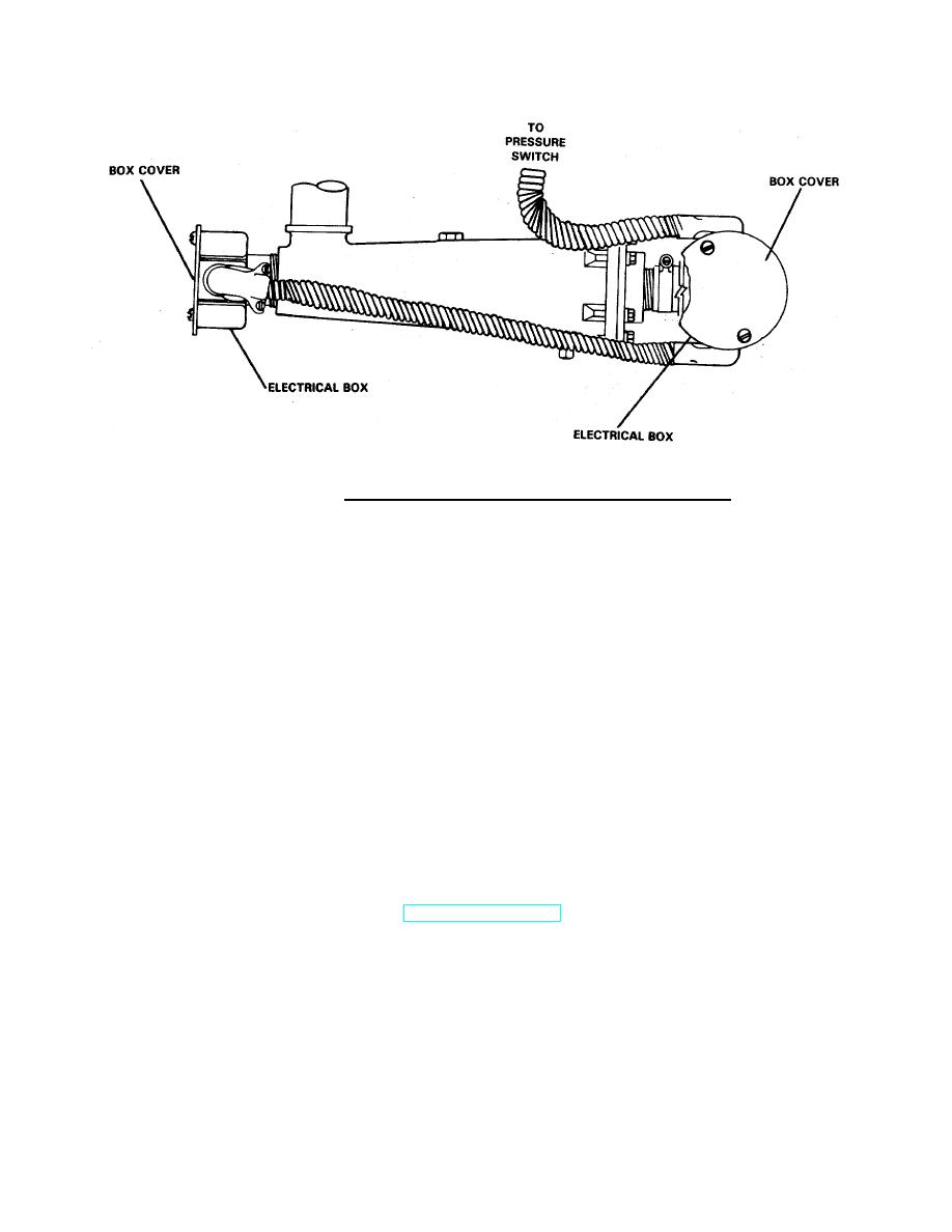
FIGURE 2-26. Location of Electrical Boxes on Coolant Heater .
d.
Install pipe to tube straight adapter (3) and tube to hose elbow (2) on pressure switch (4).
e.
Connect nonmetallic hose assembly (7) to tube to hose elbows (2 and 11).
f.
Connect electrical wiring to pressure switch (4).
g.
Install pipe to hose straight adapter (23) on engine coolant heater (21).
h.
Assembly nonmetallic hoses (25 and 29), heater tube (27) and hose clamps (30, 28, 26 and 24) and
heater tube (27). Install this assembly on pipe to hose straight adapter (23) and transfer tube (1).
Tighten hose clamps to 35-45 in-lb torque.
i.
Install loop clamp (10) on heater tube (27) and secure with capscrew (8) and lockwasher(9).
j.
Install pipe to hose straight adapter (18) on engine coolant heater (21).
k.
Assemble two nonmetallic hoses (16), heater tube (14), and hose clamps (17, 15, 13, and 12). Install
this assembly on pipe to hose straight adapter (18) and engine outlet. Tighten hose clamps to 35-45 in-
lb torque.
1.
Fill the engine cooling system. Refer to TB 55-1900-207-24.
NOTE
Refill the engine heater outlet line disconnected at the engine until outlet line is
full of coolant. This eliminates airlocks in the heater and hoses. Connect outlet
line to engine and finish filling engine.
2-102
|
||
|
||


