
| Tweet |

Custom Search
|
|

|
||
 TM 55-1905-223-24-5
(3)
Injector Adjustment, Dial Indicator Method (Non Top-Stop Injector Only).
(a)
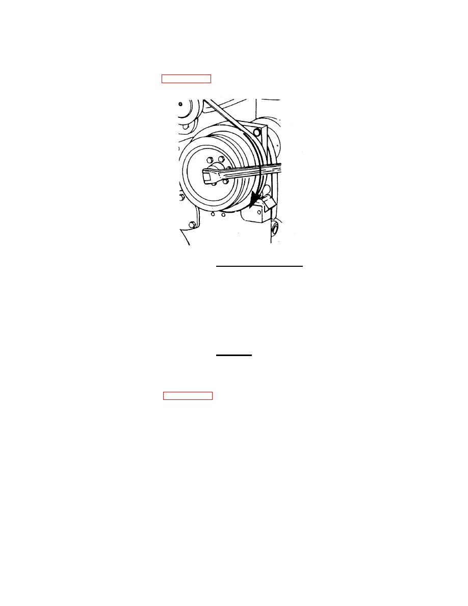
Rotate the accessory drive until the "A" valve set mark on the accessory drive pulley is aligned with the
pointer on the gear cover (FIGURE 2-39).
FIGURE 2-39. Rotating Accessory Drive.
(b)
Check the valve rocker levers on cylinder No. 5 to see if both valves are closed.
NOTE
Both valves are closed when both rocker levers are loose and can be moved
from side to side. If both valves are not closed, rotate the accessory drive one
complete revolution; align the "A" mark with the pointer again.
CAUTION
To prevent damage to the indicator and to avoid getting an incorrect reading,
install the dial indicator extension so that it clears the rocker lever.
(c)
Install the dial indicator (6, FIGURE 2-40) and the support (4) from the injector adjustment kit so that
the extension (5) for the dial indicator (6) is on top of the injector plunger flange on cylinder No. 3.
(d)
Secure the thumbscrew (1) and capscrew (2).
(e)
Loosen the thumbscrew (3) and lower the indicator (6) against the injector plunger flange until the stem
is fully compressed.
(f)
Raise the indicator (6) approximately 0.025 inch (0.653 mm) and secure the thumbscrew (3) to hold the
indicator (6) in position.
2-120
|
||
|
||


